Digital PIC18F4455 multimeter is nowadays the most used measuring instrument for electrotechnical measurements. For users, the advent of digital multimeters meant above all reliability and instrument for measuring all common electrical parameters. Users’ claims However, this device is constantly growing and with the massive expansion of computer technology begins to be a new requirement to connect the multimeter to the computer.
the design of a PIC18F4455 multimeter with the parameters specified in table 1. The design required the use of a minimum number of components at Maintaining good overvoltage protection. The connection of the multimeter and the computer is realized today the most widespread USB bus. The communication is based on the HID standard for which it is possible use the standard system driver.
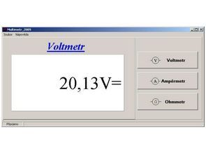
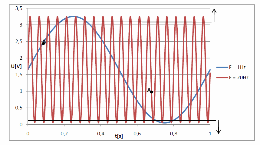
the PIC multimeter could be significantly miniaturized due to the absence of a measured value display and multimeter controls. The interconnection gives rise to new functions, such as the possibility of storing measured values values, displaying the course of the measured quantity or the possibility of long-term measurement displaying a graph of the measured quantity development.
Voltage
DC => Range: 500mV to 400V
AC => Range: 1V to 250V Frequency: 1Hz to 1000Hz
Method of measurement: RMS
Current
DC => Range: 1mA to 200mA
AC => Range: 1mA to 200mA Frequency: 1Hz to 1000Hz
Method of measurement: RMS
Resistance Range: 1 to 1M
The PIC18F4455 microprocessor program was created based on the USB communication template provided by Microchip for a faster implementation of the USB bus into the device using PIC18F4455 microprocessors. As a result, the only change made to tuned USB communication was definition of external USB transceiver.
The PIC18F4455 microprocessor contains a 10-bit A / D converter. An analog signal is possible bring to 13 pins representing the A / D converter input where each pin is separately protected by diode limiter. To convert the analog signal to digital equivalent, software reference needs to be determined. Selecting a reference defines the range input voltage. The PIC18F4455 microprocessor allows you to select an internal reference that is positive the part related to the power supply of the VDD PIC18F4455 microprocessor and the negative part to the ground microprocessor VSS. Another option is to attach an external reference, which is attached to the pins VREF + and VREF-. Adding an external reference will limit the number of pins for connecting the analog signal on 11. The N-bit representation of the analog input signal is stored in registers ADRESH and ADRESL. Software alignment can be selected right or left alignment
Schematic PIC18F4455 Multimeter Circuit

When processing this bachelor thesis, I got acquainted with the USB and USB bus communication protocol HID. I have chosen a suitable microprocessor for application into USB multimeter. I designed circuit diagram and printed circuit board of USB-multimeter. After I started USB communication and I wrote microprocessor software for voltage, current and resistance measurements. Furthermore, I created a control program that is designed to control measuring part and display of measured value.
When comparing the designed multimeter with the exact Instek multimeter, I found that when voltage and current measurement is maximum error 0.3%. I consider this fact great result. On the contrary, measurement of resistance using a current source is rather informative. For accurate measuring bridges are used today to measure resistance. Comparing the resistance values measured USB multimeter with resistance values measured with an Instek multimeter turned out to be if the measuring part is well calibrated, the method of measuring resistance is achieved using current maximum error 0.6%.
A considerable disadvantage of the proposed multimeter is the magnitude of the input resistance when measuring Tension. An input resistance of 650k is a very bad value per voltmeter. On the contrary the advantage of the proposed whole is the possibility of further extension of the management program, for example by: saving or reading the measured data, displaying the measured data in a graph, measuring extension temperature or even creating a simple version of the oscilloscope.
![]()
FILE DOWNLOAD LINK LIST (in TXT format): LINKS-26299.zip


Circuit multimètre USB PIC18F4455
Le multimètre numérique PIC18F4455 est aujourd’hui l’instrument de mesure le plus utilisé pour les mesures électrotechniques. Pour les utilisateurs, l’avènement des multimètres numériques signifiait avant tout fiabilité et instrument de mesure de tous les paramètres électriques courants. Revendications des utilisateurs Cependant, cet appareil est en croissance constante et avec l’expansion massive de la technologie informatique commence à être une nouvelle exigence pour connecter le multimètre à l’ordinateur.
la conception d’un multimètre PIC18F4455 avec les paramètres spécifiés dans le tableau 1. La conception exigeait l’utilisation d’un nombre minimum de composants pour maintenir une bonne protection contre les surtensions. La connexion du multimètre et de l’ordinateur est réalisée aujourd’hui sur le bus USB le plus répandu. La communication est basée sur la norme HID pour laquelle il est possible d’utiliser le pilote système standard.
le multimètre PIC pourrait être considérablement miniaturisé en raison de l’absence d’affichage de la valeur mesurée et des commandes du multimètre. L’interconnexion donne lieu à de nouvelles fonctions, telles que la possibilité de stocker des valeurs de valeurs mesurées, d’afficher le cours de la quantité mesurée ou la possibilité de mesure à long terme affichant un graphique de l’évolution de la quantité mesurée.