PIC Microcontroller with multi-voltage measurement, display (LCD) a good example for software pic basic prepared with pic18f4455 RE3, RA0, RA1, RA2, pins and the 4-channel voltage measurement can be made circuit as an example 5 …. 12V DC Voltage used higher voltages You may need to use a voltage divider resistors. Measuring DC voltage in the range from 30VDC 0VDC
PIC18F2550 Voltage Monitor Circuit

Multi-voltage measurement with PIC Microcontroller, a good example for display (lcd) software is prepared with pic basic, pic18f4455 RE3, RA0, RA1, RA2, 4 channel voltage measurement can be made with pins, for example, dc voltages between 5….12v are used in the circuit, higher voltages are used. It may be necessary to use voltage divider resistors for DC voltage measurement from 0VDC to 30VDC
Goals in this test app:
– Measuring DC voltages in the range of 0VDC to 30VDC.
– Uses the Built-in A/D converter from the PIC18F4455/PIC18F2550 series.
– Measures different DC voltages simultaneously.
– It makes the measurement without using an external ref voltage.
– Size: 5V DC
– Size: 9V DC
– Size: 12V DC
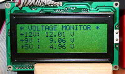
– Displays voltages on a 4-line character display in 4-bit mode
Features:
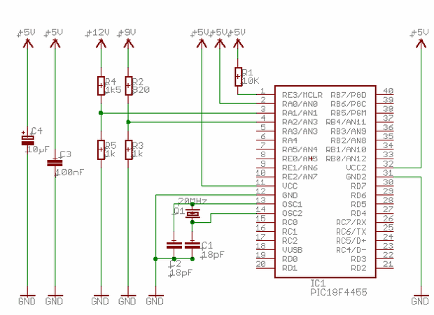
Used Microcontroller: PIC18F4455
Xtal: HS, 20MHz
Language Used: PicBasic
I was thinking of using the well known and simple voltage divider that uses resistors to measure voltages higher than VCC (the supply voltage of ?C). The maximum voltage the controller should measure is 5 VDC maximum (remember: the controller’s VCC is 5V)
The formula for calculating the correct resistance value and voltages (5 VDC) is as follows:
VR2 = Vsupply * (R2/Rtotal)
For 12 volt measurement it looks like this:
V supply = 12 V
Rtotal = R1 + R2
Rtotal = 1500 Ω + 1000 Ω
Rtotal = 2500 Ω
VR2 = Vsupply * (R2/Rtotal)
VR2 = 12 V * (1000 Ω / 2500 Ω
VR2 = 4.8V
For a 9 volt measurement it looks like this:
V supply = 9 V
Rtotal = R1 + R2
Rtotal = 820 + 1000
Rtotal = 1820
VR2 = Vsupply * (R2/Rtotal)
VR2 = 9 V * (1000 / 1820 )
VR2 = 4.94V
It is possible to do something with the computation in the microcontroller to optimize it.
To measure the voltages higher then the VCC (supply voltage of the ?C) i was thinking of using the well-known and simple voltage divider using resistors. Discover the possibilities of measuring DC voltages in a range from 0VDC to 30VDC. Use the Onboard A/D converter from the PIC18F4455 or PIC18F2550 range. Measure different DC voltages at a time. Try to do the measurement without using an external ref voltage.
– Measure: 5V DC
– Measure: 9V DC
– Measure: 12V DC
– Use Xtal
– Display the voltages on an 4-line char display in 4-bit mode
Source innovativetechnology.nl Multi-Voltage Meter picbasic pro source code schematic alternative link:


Vocoder Circuit Change the Sound
summarizes examples of a circuit that can change the sound effect on audio file will give more or less the idea of a device called circuit Okita vocoder clone ..
Voice coder circuit are all sources of PCBs, drawings, bill of materials .. Circuit diagram consists of three sections headphone amp section is a quality simple circuit can be used in different applications