For a long time, I wanted to make something out of a large array of lights but wasn’t sure how to connect up a large number of them when microcontrollers do not have enough output pins for each light. From the Internet, I learned that the same persistence of vision tricks that are used to make a CRT display work could also be applied to LEDs in a grid pattern. I started with a very simple display that displayed the time and date. Then I realized that I have an automated weather station and maybe I could send weather data to the display from via a RF link. I built two perfboard/punchboard versions before reaching this version which is made fully out of manufactured printed circuit boards.
The concept behind persistence of vision is that if a bright light is flashed the light will be perceived as being lit for a long time. If the light is flashed rapidly enough ( 60Hz in this display ), it will be perceived as being constantly on. The display uses this trick to allow a small number of lights to be on at a time.
The lights are arranged in a grid pattern with all the lights in a column sharing a positive terminal and all the lights in a row sharing a negative terminal. All that is required to light a light is to turn on the column and row for that light. The downside is that either only one row of one column may be on at a time, but looping through the grid from left to right and top to bottom with only a small number of lights needing to be on at a time and using a small number of data pins.
A mini-itx PC running Windows XP retrieves the weather conditions from my Lacross weather station via a serial interface, processes and records the data, then sends it to the three displays I have in my house via a USB connected RF module. The RF module hardware is identical to my PINGPONG-CDC unit except the module has a different firmware. BTW, the mini-itx computer also runs this web site.
Scrolling Display HARDWARE
Building large complex boards is very risky. If anything is wrong with the board, the entire board needs to be discarded sometimes after expensive components have been soldered onto them. Instead of have one big board, the display is split into module boards. These modules are the LED PANEL ( front panel with the lights and buttons ), LED DRIVER ( hardware to switch on and off the rows and columns ), and the PROCESSORBOARD ( the board that contains the RF circuitry and microcontroller ). If something goes wrong with one of the boards, only that board needs to be redesigned or replaced. A secondary bonus is that the processor board can be redesigned for a different PC connection. An example would be a module with a USB connection to a PC rather then an RF link for cost savings.
Scrolling Display LED PANEL
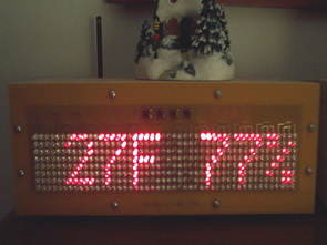
The LED PANEL contains the LEDs and the tactile switches. The LEDs are red high intensity LEDs ( Jameco part # 333526 ). The LEDs are arranged in a grid of 48 columns by 8 rows. The columns are grouped into groups of 4 each of which has a 4 pin Molex header ( part # 22-23-2041 ) to connect it to the LEDDRIVER module. The rows are also grouped into two groups of 4 connected by the same Molex header part number as the columns. The switches are arranged in a 2×2 grid and are connected via a 4 in Molex header directly to the PROCESSORBOARD. The LED PANEL is completely exposed and is fastened to the wood enclosure via #6 screws.
Scrolling Display LED DRIVER
The LED DRIVER module controls the individual columns and rows of the LED PANEL. The core of the module is 4 16 bit MCP23S17 SPI port extenders. 3 of the extenders drive the columns and one of the extenders drivers the rows. The column extenders are connected via 150ohm resisters and the row extender is connected via a ULN2803A 8 bit darlington array. . The LED DRIVER is connected to the PROCESSOR board via a SPI connection. The LED DRIVER module is mounted on the inside face of the back enclosure board via #6 screws and plastic spacers.
The core of the processor board is a Microchip PIC18F2620 microcontroller clocked at 32MHz. The RF receiver is a LinxTechnologies HP-3 receiver. The PIC18F2620 is connected to the RF receiver via the microcontroller’s UART and connected to the LEDDRIVER module via the SPI port. The PROCESSORBOARD is mounted on the outside of the backboard of the enclosure with the component side inside the enclosure and the back of the board exposed. The back ( solder side ) contains the antenna, debugger, and power jacks. Power is supplied via a 5v regulated wall wart.
Columns 48
Rows 8
LEDs 384
Refresh Rate 60Hz
Supply Current 200mA
Aproximate Cost $358
The main source code file of the firmware is main.c. As usual, the firmware uses all three priority levels available to the processor. The high priority interrupt is responsible for incrementing the millisecond clock, scanning the keypad for key state changes, and handling new bytes on the RF connection. The low priority interrupt is responsible for scanning the display data bitmap and loading the MCP23S17s depending on the byte that is to be displayed. The main body of the code is responsible for scrolling data and building the bitmaps which are loaded by the low priority interrupt. Double buffering is used to ensure the display state doesn’t change in the middle of a LED scan. As one bitmap is being displayed, another bitmap is being created.
The RF data is a simple fixed length packet. The start of a packet is 4 magic values, followed by the display data, and then ends with checksum. If the magic doesn’t match or the checksum is incorrect, the data is discarded. The RF connection is a simple unidirectional connection that uses a static channel which is configurable from the display unit. The transmitter is not constantly on. It powers off when not updating the display.
The display has 5 different modes of display which are selected randomly. Each mode has a different function in the firmware that is named the same as the mode. These are Static Clock( a static display which displaced the current time ), StaticWeather ( a static display of the outdoor temperature and humidity ), ScrollingClock ( scrolling display of date and time along with the sunrise and sunset time for the day ), ScrollingWeather ( scrolling display of outdoor climate temperature, temperature extremes, humidity, pressure, and rain ), and ScrollingIndoorWeather ( indoor temperature, indoor extreme temperatures, and humidity ).
Source: http://www.raccoonrezcats.com/ Complete Hardware Details: Schematics and Board Layouts ( PCB123 and Eagle ) Plus BOM alternative link :


Adding a Larger Antenna Modified Wifi Router
If Wifi Router design gives you hands to strengthen domain to upper antenna can be installed with a good view over workmanship without breaking your Router can be more effective
First off equipment may interfere there for the warranty canceled Note that this transaction line and the supply connections of the structure without the new WiFi antenna to attach SMA connector on a small soldering process have shorted one careful not to. summary instead of the original antenna SMA connector is placed disassembled and can be attached to the antenna connector on the desired