Now you have to wonder to advanced pic controller was quite popular among them PIC18F2550 USB pic18f2520 a good example on how to control the output with the MOC3042 opto triac driver output isolation is being provided and TIC236M working with the 220v loads can be controlled
Source article with triac drive circuit used in the lamp up to 100W without cooling, heating and so on. As indicated loads can be controlled with a coolant 10A (2300W) also isolated driver circuit that can be used in the other controller output

As I said, the source could limp ccs c code circuit diagram of a control program has been prepared with the visual basic. Exe package and source codes given, etc. pic pc communication visual basic example would be to
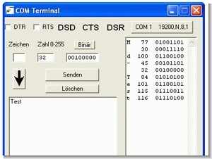
COM terminal allows you to send and receive serial data on the serial interface of the PC RS232. Adjustable serial ports are COM1, COM2, COM3, COM4. All possible baud rates, parity, number of bits can be set. The serial port settings are saved in an ini file. For new start the terminal program, previous settings are effective.
Unlike other terminal programs: To send any-way 8-bit word by serial port. As input characters (A), the number (0 .. 255), or binary (00001111). -Received data will be output in three formats. -It is a condition of wires DSD, CTS, DSR displayed (black is 0, red is 1). Control lines DTR, RTS are switchable. -A range of characters can be transmitted, wherein the time between sending each character can be set in ms.
COM Terminal Program

Than 8 switch outputs Port B of the PIC18F2550 is used. Power gets the circuit from the USB port. Power supply is separate from the microcontroller and the computer galvanically. switching signals USB socket intended as a virtual serial port COM4. To turn on the first load, send “E1” to turn off “A1” This can be done with any terminal program. Or even easier with a BAT file. ECHO E3> COM4 This turn of the third load.
If you use a triac to the heat sink, consumers can receive up to 10A (2300W). Without heat sink enables you to weigh up to 100 watts. E.G. a lamp. Note the heat sink under voltage (230V) is available. In addition, here is single-pole disconnection. That means current is switched off, voltage remains. Pull for repairs to the consumer mains.
Addendum. I’m reinventing the wheel completely stupid second time. When it accumulates give beautiful solid-state relay. E.G. S202 S02 (current to 8A with the heat sink) Resistance calculation for connection to 5V (5V-2, 2V) / 8mA = 350ohm Minus the mass. Plus over 330 ohm resistor to pin PBx.

Mischaka USB Bootloader
This bootloader + PIC18F2550 is practically the same as an FTDI chip + PIC. The bootloader regulates the USB communication of the user program. The basic idea: a bootloader that is used jointly by the USB communication routines, the user program, and the bootloader.
With this bootloader you can use the USB interface from the user program. You don’t have to deal with USB programming. This means that beginners can also use USB.
Policy: The bootloader creates a virtual serial interface. The PC waits for 1 second for the bootloader part and then goes to the application program. The virtual serial interface is preserved. If a character is to be sent from the user program via USB, a function in the botloader field is called. CALL 0x0F08
and the function to send to USB from address 0x0F08.
On the PC, look in the device manager under Connections under which number the Michaka port was created (for me it was COM4). Then start any terminal program and you can immediately communicate with your application in the PIC.
Another advantage of this system. It is independent of the programming language and the compiler. You can program in the assembler and use the bootloader’s USB functions. The only action is that the user program starts from the right place and does not write to the allocated RAM space.
Features:
Reset vector 0x1140 User program is started here
Interrupt vector 0x1148 high priority interrupt
Freely available memory (RAM) 1344 bytes
Overwrite protection of the bootloader is implemented on the PIC partition and the PC partition. The data contained in the hexadecimal file at address 0x1140 will not be flashed.
Limitations:
USB interrupt is used. The user cannot disable interrupts for longer than 10mS. Otherwise, the PC disconnects the USB device.
Low priority interrupt is not supported.
The bootloader cannot write to EEPROM or configuration bytes.
The system clock is fixed at 48MHz. Quartz is 20MHz.
COM terminal Program
The COM terminal enables sending and receiving of serial data on the serial interface of the RS232 computer. The configurable serial ports are COM1, COM2, COM3, COM4.
All possible baud rates, parity, bits can be set. Serial port settings are saved in an ini file. When you restart the terminal program, the previous settings will take effect.
Difference from other terminal programs:
-Possibility to send any 8-bit word via serial port.
-Enter as character (A), number (0…255) or binary (00001111).
-The received data is also output in three formats.
-Status of DSD, CTS, DSR lines is displayed (black 0, red 1).
-Control lines DTR, RTS can be changed.
-A range of characters can be sent, so the time between sending each character can be set in ms.
When starting the program, the COM port opens. If the COM port is already used by another program, the program will display an error message. You have the possibility to open another interface. If a character is specified, the ACSII value and binary value are displayed automatically. When specifying an ACSII value, characters and binary values are automatically displayed. Please press BINARY to display a binary value as a character and ACSII.
By pressing the SEND button (above) you start the transmission of the character. Instead of the SEND button (above), you can press Enter when the cursor is in the “Character” – input field or “Number” – input field. The SEND button (Below) starts the transmission of the text.
With the OK button, you have the option of transferring a character from the “Character” input field to the text input field. This function can also be used to send binary values as strings. The DELETE button deletes the output field.
The program is mostly designed to communicate with the microcontroller or experiment with other devices: serial mouse, GPS receiver, modem. The COM terminal cannot send or save files, but there are many other programs for this, for example TTermpro.
cc5x.de/ PIC18F2550 USB isolated Triac Control CCS C Visual Basic project schematic ccs c source code program files alternative link


12V to 220V Sine Wave Inverter Circuit SG3524 230W
230 Watt sine wave inverter SG3524 PWM control circuit integrated in the project used a lot in various power UPS uninterruptible power supply on the market I have ever seen in an inexpensive components to bolc
The inverter circuit 12 volt + entry in the D1 diode reverse polarity protection ensures after the LM741 opamp made with low-voltage detection circuit, this chapter battery voltage of 10.5 volts drops below PK1 relay and stops functioning for cooling fan control section also LM741 made by
CNY17 opto with 220 volt ac output voltage is stable solids added to the feedback provided to the collapse load is connected to 220v ac output