PWM Motor control circuit MC34063 switching dc dc regulator is used to supply pic16f88 microcontroller 4 mosfets are driven with PIC (IRF1405) EMF control is also made with PIC for better speed control, there is also a 4 digit display indicator pic16f88 works with 8mhz 12V 24V Motor Speed Control circuit motor It consists of 2 parts as control and indicator.
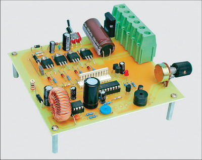
12V-24V High Current DC Motor Speed Control
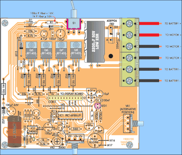
The 12V or 24V high current DC Motor Speed Control circuit is rated at 40A (continuous) and is suitable for heavy duty motor applications. All control tasks are done by pic16f88 microcontroller.
The circuit has features such as Battery monitoring, soft start and speed regulation. It also monitors the speed adjustment potentiometer and drives a 4-digit display board with two buttons.
Main features of DC Motor Speed Control circuit
- Advanced speed regulation under load
- Automatic soft start and fast shutdown
- Eight memory settings
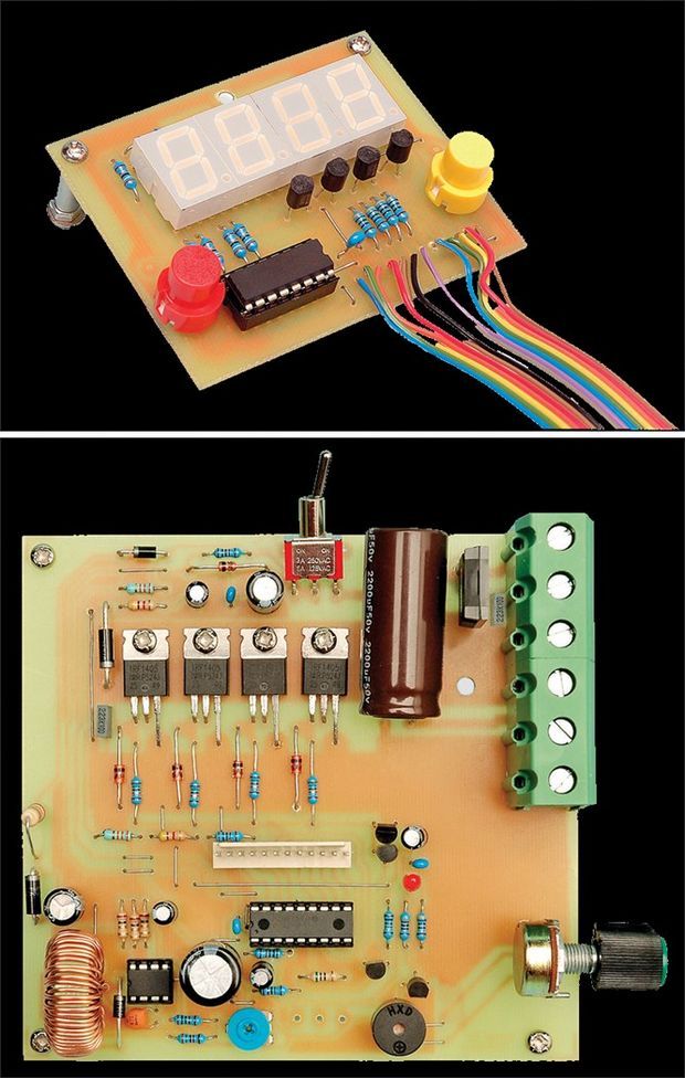
- 4-digit 7-segment display
- Variable frequency (PWM) for pulse width modulation
- battery level meter
- Low Battery alarm
- Persistent settings and defaults
- Continuous operation up to 40A current
The 4-digit graphics card is optional, but we strongly recommend that you do it, even if you’re only using it for initial setup. Unlocks all the features of the speed controller and allows all settings to be adjusted. The PIC16F88 Microcontroller will detect if the video card is connected, and if not, the drive will only support basic functions. In this simple mode, it functions as a simple speed controller with automatic soft-start and speed controlled directly by the pot (VR1). All other settings will be the initial defaults or the most recently set (with the video card connected).
When connected, the 4-digit display lets you monitor speed and input voltage (useful when working with a battery). It also lets you navigate through various menus to adjust settings.
The circuit can run from 12V or 24V batteries and can drive motors (or resistive loads) up to 40A. It also provides speed regulation under load.
In drives that do not have good speed regulation (ie the vast majority of designs), the more the motor is loaded, the slower it gets. To provide speed regulation, the circuit must monitor the motor’s EMF because this parameter is directly proportional to its speed.
As a result, our speed control circuit monitors the back EMF of the motor. “Back-EMF” is the voltage opposing the current flowing through the windings by any motor. EMF stands for “electromotive force” and is an old term for voltage. Back-EMF is directly proportional to motor speed and therefore by monitoring this parameter we have methods of controlling and maintaining motor speed.
In practice, the microcontroller’s main control loop tries to match the speed of the motor (back-EMF) with the speed set by the pot or recalled from a preset memory. If the measured speed is lower than the set speed, the duty cycle of the pulse width modulation (PWM) signal used to drive the Mosfet power that controls the motor gradually increases. In other words, if the speed tends to decrease, more power is supplied to the engine and vice versa.
The frequency of pulse width modulation can be adjusted from 488Hz to 7812Hz. This is a useful feature as different motors will have different frequency responses as well as different resonant frequencies.
By now you are probably wondering how the microcontroller monitors the back EMF of the motor, taking into account that the motor is driven by DC with continuous pulse width modulation. The answer is that the micro-EMW periodically turns off the PWM signal to the motor just enough time for it to stabilize.
There is a low battery alarm to warn when the battery level drops below a preset value. This is particularly useful for applications such as electric wheelchairs.
There are also eight memory speed settings. All settings are permanent, meaning they are kept in internal memory.
Source: http://www.siliconchip.com.au/cms/A_110345/article.html 12V 24V Motor Speed Control Circuit schmeatic pcb PIC16F88 pic assembly source code alternative link:


Wav to PICmicro ASM, C Converter Program
PIC or other micro-controllers, sound files to upload wav format files PIC Assembler ASM and PIC microcar C code a program that converts have all the details (in english) is a simple additional circuit and the PIC outputs how kullanılag is described, circuit resistance 2 looks to be the general 2Ω is perceived as attention Get the names of two resistance values were recorded only in the code file writes
Wav to PICmicro Converter