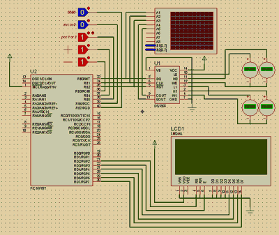
Prepared by: oaycan Maxim DS1868 (Digital Potentiometer) and PIC 16F877 Usage Proteus isis Simulation We will make a digital potentiometer using Maxim’s DS1868 dual digital potentiometer IC and PIC 16F877. With this application, you will be able to select one or two digital potentiometers and change the 10K value.
Digital potentiometer applications are used in almost all electronics industry, from volume control to mobile phones. With this document, you will be able to see the structure of the DS 1868 digital potentiometer element, its leg connections, how it works, and its operation by simulating the PIC 16F877 and DS 1868 sample circuit and proteus library model realized in proteus.
The PIN description of DS1868 and the structure of the pots are given in the figure below. DS 1868-10 (10K), DS 1868-50 (50K) and DS 1868-100 (100K) options are available.
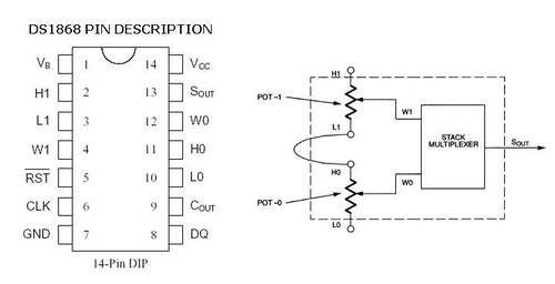
Maxim DS1668 Pin definitions
L0-L1: bottom ends of the pot
H0-H1: upper end of the pot
W0-W1: middle end of the pot (set end)
RST: serial port reset input
DQ: serial port data input
Clk : serial port clock input
Cout: cascade port output
Vcc: +5V supply
Gnd : earth connection
Sout: Stack Multiplexer output
DS1868 Dual digital potentiometer features
• Ultra low power consumption
• 256-state potentiometer with two digital controls
• Reading and setting defined by Serial port for two potentiometers
• Resistors can be connected in series to obtain high resistances.
• +5 or +3 volt operation
• Standard resistance values
• DS1868-10 10K
• DS1868-50 50K
• DS1868-100 100K
The selected digital potentiometer takes the adjustment tip to the middle point.(50/50)
It starts the selected Digital potentiometer setting tip value from 0.
Digital potentiometer selection (1st or 2nd dig. Pot.)
When the (+) button is pressed, it increases the value of the selected potentiometer step by step.
When the (-) button is pressed, it decreases the value of the selected potentiometer step by step.
This resistance value can be read between the two ends by connecting an ohmmeter between (L0 – W0) (H0-W0) and (L1 -W1) (H1-W1) connections. At the same time, the position of both digital potentiometers (in which step) can be seen on the LCD display.
Using DS1668

Before starting the simulation, the zip file
• Put the files in the LIBRARY folder into “C:\Program Files\Labcenter Electronics\Proteus 6 Professional\LIBRARY”;
• When you load the files in the MODELS folder into “C:\Program Files\Labcenter Electronics\Proteus 6 Professional\MODELS”, the DS1868 IC will be defined in the Proteus program.
• Then run the DS1868.dsn file prepared with the Proteus 6.7 sp3 program and ensure that the DS1868.HEX file is in the same folder.
• Now you can easily simulate the digital potentiometer.
Using DS1668 Digital Potentiometer proteus isis DS1668 library schematic simulation hex files


20Hz 25kHz Subwoofer Amplifier Circuit TDA1514A
20 Hz to 25 kHz TDA1514 amplifier integrated subwoofer amp used in the cabin floor bass filter TLC272 opamp used symmetrical +-27v supply voltage to feed the olrak opamp zener diode made R12 regulated.
TDA1514A TLC272 20Hz 25kHz RMS 32Watt TDA1514A Aktivbox – This NF-performance amplifier module is equipped with a 230-V power supply equipment and provides 32 W / sinus an 8-ohm speakers. The module is designed for the rear Installation in loudspeakers designed so that a simple way Aktivbox powerful.