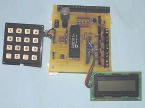
Security Alarm project 16f877 microcontroller Board 2×16 lcd indicator alarm circuit connected to the keypad on the necessary adjustments can be made. Circuit diagram pcb drawings, asm source, hex codes, alarm installation, lcd menu information (in English). Alarm circuit 8 pieces TRIAC output connect this outputs relay can be controlled by a variety of devices such as elements.

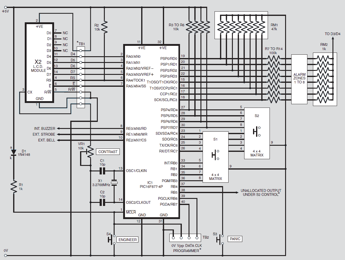
The PIC16F877 microcontroller IC1 is the load of the entire system. In the input mode RD0-RD3 and RC0-RC3, used via the port pins, the PIC can monitor between one and eight sensor zones plus an extra “Panic” zone via RB4. The amount is selected by the user.
Alarm Outputs Four audible/visual alarm control outputs are provided, three via pins RE0-RE2 and one via RB5. When activated, these pins go high and are specifically designed for the following purposes: an internal buzzer (RE0), an external strobe (RE1), an external buzzer (RE2) and any user-selected outputs that can activate these devices (depending on their type) directly or via power transistors TR1 to TR4. In the event of any alarm, the buzzer, strobe (if present) and the buzzer are activated.
This buzzer remains active for a preset time (and is automatically stored by the user via software), with a maximum time of 20 minutes. The software will block any unauthorised zone entry without rebooting (but see Panic Switches later). Once the alarm system has been activated it can (normally – also see later) only be reset by entering the correct PIN code.
Monitors one to eight entry/exit points (zones). building or room
Turns off activated bell after preset time to prevent disturbance
Allows users to enter/exit a timed zone (timeout) without triggering
Allows required zones to be fully monitored after timeout period has expired
Allows users to terminate timeout procedure
Allows users to control monitoring system
Allows users to change PIN code
Allows users to access control system without using PIN
Keeps battery fully charged when mains power is available
Prevents bell from being activated when power is restored
Shows if zones have been entered for later viewing
Allows fewer zones to be monitored than available
Automatically recognizes if a sensor needs to be monitored
Allows open-circuit or closed-circuit sensors to be used without being used
Recognizes if a sensor has been falsely opened or closed in advance.
Allows users to preview zone sensor status
Allows the bell-on time to be set for a shorter period than the specified time.
Prevents the bell-on time from exceeding the UK limit
Allows users to control the system via indicator lights
Allows indicator lights to show the status of the power supply
Provides tamper alert against interference with the system
Provides a “Panic” button that immediately activates the chime
Provides “passive” advice (e.g. buzzer) that a zone is being stolen
Provides an optional auxiliary keypad with a separate PIN for attachment.
Source: http://elektron.uw.hu/


Oscilloscope Circuit with MAX492 PIC16F877 Graphic LCD
Oscilloscope circuit project pic16f877-20 (20 MHz) microcontroller based on X 1, x 10 entries MAX492 Rail-to-Rail Op Amp input via grilimi 5v indicator as 128 × 64 glcd (PG12864) graphic lcd. Oscilloscope circuit power supply 9v dc
The application schema, the circuit source assemly asm, hex codes for detailed description.
what is the password to open files
password for all files: 320volt.com