There are source codes, schematics and pcb files of the project that used 16f84a microcontroller in the speedless alarm circuit. Speed Alert for Cars Does your license seem a bit compromised? This compact speed alarm will help you obey speed limits.
Anyone who drives will inevitably exceed the stated speed limit from time to time, either on purpose or due to lack of attention. But these days, speeding isn’t really a good idea. Aside from the obvious safety considerations, there are plenty of speed cameras around and it’s easy to get a hefty fine or even lose your driver’s license.
On a long journey, your speed may increase gradually as you get used to the road conditions. It’s also very difficult to stick to the speed limit in the 60km/h zone after driving at high speed on the open road – 60km/h seems agonizingly slow after driving at 100km/h.
In this case, a speeding alert can keep you alert and keep you within the specified limit. Another situation where it’s easy to accidentally exceed the speed limit is if you’re using cruise control.
Now, while cruise control is very helpful when it comes to maintaining the set speed, they have an inherent limitation – on downhill roads the vehicle’s speed can exceed the set limit. Once again, a speed alert can instantly alert you when you exceed the limit.
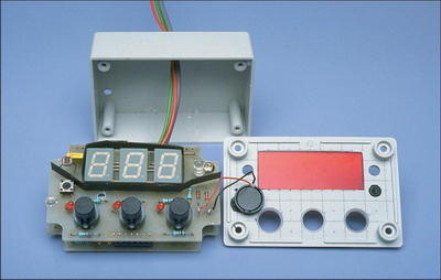
Our new Speed Alarm is very compact and fits neatly in the smallest box available. All parts fit on two small PC boards housed in a compact plastic case.
So how did we manage to shrink the circuit so dramatically? The answer is that we replaced all the discrete control circuits with a low-cost PIC microprocessor and found the necessary software to control the internal “intelligents” of this device. The resulting circuit fits into two small PC boards stacked inside the case.
It’s just as easy to drive as before. As shown, the front panel has a 3-digit LED display, an LED indicator and three pushbutton switches. Two of these buttons allow you to set the alarm speed from 0 km/h to 155 km/h in increments of 5 km (one switch increases speed, the other decreases).
As soon as you exceed the preset speed, the indicator LED lights up and a built-in piezo alarm beeps briefly at 10-second intervals, giving a warning.
The third switch selects between three display modes: (1) alarm rate value; (2) actual vehicle speed (ie, the unit functions as a digital speedometer); and (3) alarm off mode. Each time the button is pressed, the unit switches to the next operating mode – it really is that easy to use.
PIC16F84A Car Speed Alarm

Source: http://www.siliconchip.com.au/cms/A_103208/article.html
Car Speed Alarm Circuit PCB schematic Display Indicator PIC16F84A pic assembly source code Alternative link:


Two-Channel Dimmer Circuit with PIC16F84A LED Level indicator
High power lamp control Maximum lamp brightness preset Minimum lamp brightness preset for filament preheating Automatic or manual dimming between brightness presets Separate flash on and flash off Flash brightness preset Dimming rate programmable from instant through to 40 seconds A and B dimming rate selection Lamp brightness indication Automatic dim up and dim down indication
PIC16F84A Dimmer Circuit