PIC16F84 stepper motor control circuit is the button to the right to the left button is pressed, the motor rotates continuously in the opposite direction to the right Doderer stop button will stop the motor.
The engine speed is adjusted by changing the setting of a frequency crystal oscillator RC oscillator instead of the value of resistor R is connected and changing the speed setting that can be added to potl
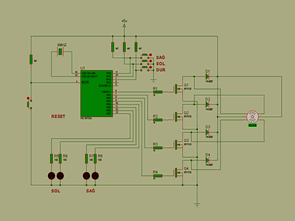
Stepper motor driver circuit diagram

Stepper Motor Control Circuit proteus simulation pic assembly source code files:
Stepper Motor Control Circuit with PIC16F84A mosfet ZIP File Password: 320volt.com


Digital Tone Control Circuit with PIC16F877 LM1036
Were made by combining the LM1036 integrated circuit PIC16F877. BASS, TREBLE, BALANCE, VOLUME settings on the LCD screen is made in my image as a 15 something in the shade echelons. In addition, this circuit easily adapted to integrate other tonkontrol eqlayz integrated holster or connected. 4 separate circuits can be added to any channel.
The working principle is very simple. Four separate 4-bit digital data is collected and converted to the number of analog output resistance of the common 0V … 5V voltages are given in 15 different stages. This voltage is applied to the input level of the integrated tone control.
Schrittmotor-Steuerschaltung mit Mosfet PIC16F84A
PIC16F84 Schrittmotor Steuerkreis ist die Taste nach rechts, um die linke Taste gedrückt wird, dreht sich der Motor kontinuierlich in die entgegengesetzte Richtung nach rechts Doderer Stopptaste stoppt den Motor.
Die Motordrehzahl wird durch Ändern der Einstellung eines RC-Oszillators anstelle des angeschlossenen Widerstandswerts R und durch Ändern der Drehzahleinstellung, die zum Potentiometer hinzugefügt werden kann, eingestellt
Schaltplan des Schrittmotortreibers