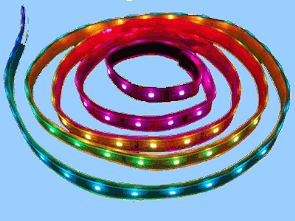
PIC made with 8-channel moving light circuit. Combine some of this circuit outputs a rgb led Ribbon. the result satisfying. Three different buttons animation circuit. Which if you hold that the animation comes in. If you connect the pushbutton switch instead of the constant animation of the animation to remain stable.
The circuit is required for the Pic16f84 microcontroller 5 volts. Works with a maximum of 5 volt pic16f84. The circuit used for working between 9-12v Led Strip is also likely to feed source. Pic16f84 microcontroller the voltage regulator IC, which is required for the operating voltage is provided. LM7805 The software that Integrated leg 100n comparisons capacitor LM7805 Pic16f84 parasites. The processor’s output is sent to the LEDs through the ports by strengthening a bc548.
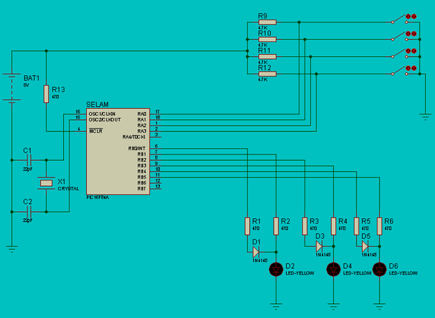
RGB Led Strip Animation isis proteus simulation of circuit diagram pcb ares drawing and software files:
FILE DOWNLOAD LINK LIST (in TXT format): LINKS-22735.zip


ENC28j60 Ethernet Module For Arduino Kit
Arduino Kits can be merged with the Arduino Ethernet module is based on the materials used in the design of the PCB DIP ENC28j60 SMD No 3 .3V regulator is used for the material, I don’t think that’s in the market rather than LD1086 LM1117-3.3 is available.
ENC28j60 Ethernet module for plenty of examples of the Arduino application, there is a list of the drawing of the PCB Gerber files, materials prepared for the program you are using, you can transfer part of the PCB gerber pressure.
Pic16f84 RGB Led Streifen Animation Schaltung
PIC gemacht mit 8-Kanal-moving-light-Schaltung. Kombinieren Sie einige dieser Schaltung Ausgänge rgb-led-Band. das Ergebnis befriedigend. Drei verschiedene Schaltflächen-animation-Schaltung. Was, wenn Sie halten, dass die animation kommt. Wenn Sie schließen Sie die Taster anstelle der Konstante animation für die animation unverändert bleiben.