USB Battery Charger Circuit Pic16f629 microcontroller integrated with the computer’s USB port 1 100-1000 The AAA battery charging circuit charging time the battery current compared to 1-14 hours of battery is full time dual-color LED and buzzer and warning is given. Besleneeg from the USB port in the circuit diagram for the circuit in 7805 will use a 5 volt regulator IC that you do not want to use the USB port with an adapter 9v 12v going to use … 7805 should be installed .. USB battery charging circuit assembly prepared with the resources of the microcontroller software. Asm and. Hex file there.
PIC16F629 USB Battery Charger

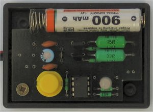
AAA battery charger with USB port
You can choose from 3 options of charging current. The number button is red LED starts flashing and adjusts the charging current and time. After charging, the green LED and audible alarm start.
Charge charge battery according to the set program. The charging time is limited and after the specified time, the charging voltage is disconnected from the battery. Setting the current time and chose this . 1 pulse is 100 mA for 14 hours, two flashes are 200mA for 7 hours, and 3 flashes are 300 mA for 5 hours.
We recommend taking into account the battery 900 mA or 1000 mA and charging 0.1 C ie one-tenth of its rated current, we also charge a current of 100 mA for 14 hours. Because its duration is too long in a certain situation, it is possible to increase the current to 200 mA, 300 mA, which shortens the charging time.
I do not recommend using more current because the charger is heated and the battery charger does not control the temperature of the battery. This battery can cause overheating and subsequent destruction. Convenient hands-on time to control the charging battery temperature and reduce it with high heating power or stop charging!
Important notice: USB devices can draw up to 100 mA from PC. The current range configuration identifier can be received only when requested and the Energy operating system confirms it. It is not charging and therefore not every PC may work.
Therefore, you may (and should) also bear in mind that the capacitor C1, which is defined as a short circuit and the USB port will draw a large current for a long time and corks unequivocally staff.
Description of operation: It turns green after connecting the adapter to the USB port of the PC. Indicates that the charge is energized and ready to charge. By pressing the button the green LED flashes every 1.6 seconds and then the red light goes out.
It will flash 2 times when pressed and 3 times after pressing . Flashing red and green lights go off, press stop and the charger is ready to charge. Every time you press the button, you will hear a beep and beep beep after charging 10 times.
USB devices may draw from the PC up to 100 mA. The larger current can subscribe only when it is requested in the configuration descriptor and Energy approves the operating system. That in this charger does not, and therefore may not work in any PC. For this reason, the mind staffed capacitor C1, which when turned on will draw a large current for a long time and fungi that can (and should) be evaluated as a short circuit and disconnect the USB port.
Source: http://www.cmail.cz/doveda/konstrukce/aku_usb/index.htm USB Battery Charger Circuit with PIC16F629 pic assembly alternative link:


Solid State Tesla Coil Circuits
Various “Solid State Tesla Coil” Mini Tesla Coil high voltage coil applications integrated project schedule based on the NE555 integrated IRF540 MOSFETs in the output is driven using a Tesla coil circuits are powered by 12v dc voltage.