I’ve done as a final project at the university tried to mikrobasic’t I wrote the program code running circuit. 99s drew to protel PCB circuit Altium Designer also can open in 2008 or 2009. circuit related issues that need attention are a few.

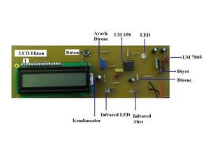
I use the LM358 op-amp is used, but better results can be obtained OP297
other matters i-led and photo transistor selection i LEDs and photo transistors operating frequencies must be equal so the outside should be tested photo-transistor outputs oscilloscope connected ir LEDs and photo transistors finger between the placing oscillating you to observe. olrak multi-turn potentiometer setpoint is quite sensitive tirmpot I’ve used. (For LM358)
Pulse Oximeter Circuit Operation Test
Pulse measurement circuit according to the density of blood is cut off measure hassayiet On concentration is done by setting the op-amp 2 Hz and actually raises six signals with very adjustable potentiometer setting, measurement points are set. Works much better if you used the electrodes . SPO2 finger electrodes on the patient monitor to measure blood oxygen saturation and pulse rate are used inside the electrode .
First commissioning When you apply power splash screen çıkıcak this order forefinger ir- LEDs and photo transistors between the insert located at the corner LEDs with blinking observe if you do not see the adjustment screwdriver with making the adjustments ( index finger ir- LEDs and photo transistors must be between ) flashing Provide .
Then push the button and eventually you will measure your pulse for 10 seconds the LCD will display the results .
Measuring Probe : does not work in hospitals is found, the status of the worn out many probes have received bi We went through them again and we’ve made it work . So our measurements appeared perfectly healthy . Let’s do our own probe not had too much trouble , especially but not created .
Author: @Ahmey AY, Gülin AKILLIOĞLU Pulse Oximeter Circuit mikrobasic source codes, protel 99se pcb source files:


AT89C52 Applications Examples Proteus isis Circuits (10 projects)
AT89C52 examples of applications can be helpful for beginners of all samples prepared with simple 3 .5 source lines of code. Bass. Hex, bin, etc.. isis proteus have codes and simulation files.
0-255 binary counter (LEDs), 0-9 counter circuits (display), 00-99 advanced counter circuits (display, 7447), 00-99 down counter circuit (display, 7447), 0-9 Multiplexed LED Display counter (one on each display again)