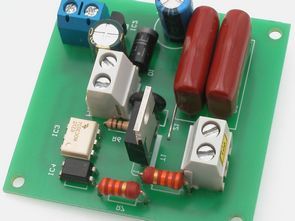
The controller allows convenient control of the intensity of lighting made of bulbs. It is not suitable for use with typical energy-saving fluorescent lamps and LEDs, unless they are adapted to work with typical dimmers. There are many similar solutions and probably every electronics engineer has performed a “dimmer” at least once, but this device is distinguished by the lack of a potentiometer, which is the most unreliable element. Also, unlike typical solutions, no noisy choke was used. Recommendations: the dimmer can be used e.g. to brighten / darken the bedside lamp in a children’s room
The lighting intensity is regulated by means of a pulse width variable width (PWM modulation). Apparently this is a well-known solution, but as it usually happens, if we think that something is uncomplicated, it means that it is not aware of the scale of the problem …
If using PWM we regulate the intensity of LEDs or light bulbs powered by DC voltage, you only need to change the width of the periodic signal with a frequency greater than the inertia of the eye. However, if the bulb is powered by mains voltage (230VAC / 50Hz), the matter is more complicated because the control signal of the bulb must be synchronized with the frequency of the network.
Otherwise, the bulb can be turned on once at the peak of the supply voltage sine wave, and in the next period at the zero crossing point, which would result in accidental changes in the brightness of the light to the rhythm of changes in the mains voltage.
Another problem is choosing the key that turns on the voltage that powers the bulb. At alternating voltage, the obvious choice is to use a triac because of the low power loss and easy control. As we know well, the triac will turn off only after the closing signal on the gate disappears and the voltage sine wave passes through 0 (voltage polarity change).
You cannot turn on the triac and expect that our controller will turn it off e.g. at the peak of a sine wave, because this will happen only when the voltage polarity is changed, i.e. a phase angle of 0 ° or 180 °. Therefore, the width modulation of the bulb supply wave must take place in such a way that, after detecting the voltage transition by 0, the timer controlling the dimmer operation measures the tripping time of the triac, and then turns it on so that the control signal on the gate is turned off before the voltage disappears between the anode and the cathode.
Failure to do so will result in triac switching for the next half period. Since the frequency of the mains voltage is 50 Hz, so the sum of time from the synchronization pulse to the loss of signal on the gate must be less than half of the period, i.e. 10 ms.
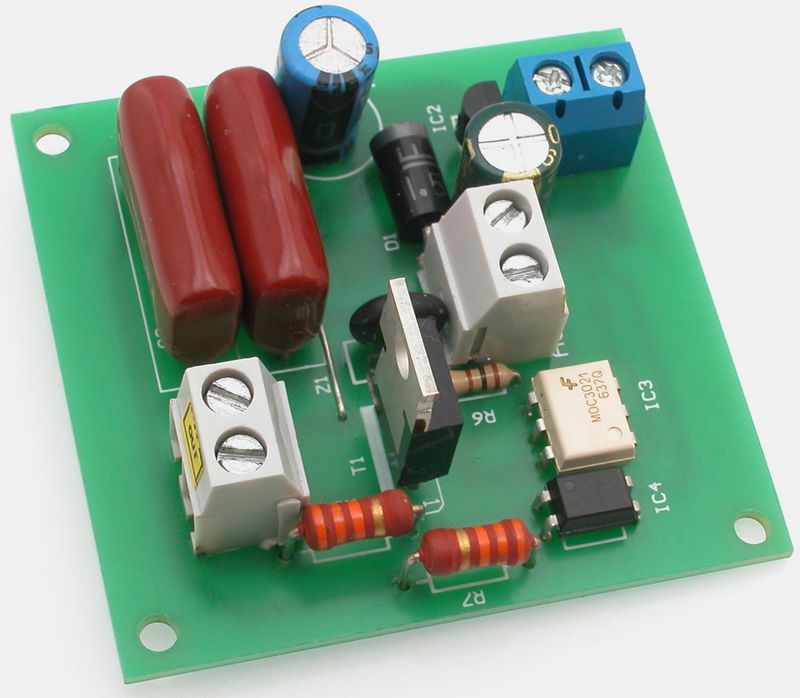
Building
Schematic diagram of a digital lighting dimmer
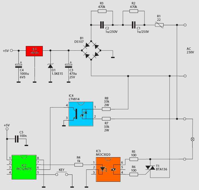
Readings of synchronization pulses, generation of pulses activating the triac and handling of the control button is handled by the PIC12F675 microcontroller. The GP1 port (pin 6 of the microcontroller) is connected to the IC4 optocoupler output of the LTV814 type.
It has two LEDs of opposite polarity on the input, which are connected in parallel. Thanks to this, there are pulses at its output each time the sinusoid passes the input voltage through 0, i.e. every 10 ms. The voltage at the optocoupler input is supplied via resistors R7 and R8.
The inquisitive electronics may think that using capacitors instead of them could reduce the power dissipated in the system, but this would cause a phase shift and, as a result, the microcontroller would receive pulses every 10 ms, but not in phase with the supply voltage.
The GP0 pin (PIC12F675 pin 7) is an IC3 optotriac, and through it the T1 executive BTA136 triac. This allows you to easily increase the current controlling the gate of the T1 executive triac and easily shift the control voltage level.
It should be noted that in this solution only the triac works without a voltage phase zero crossing detection system, so for example MOC3020 or MOC3021. The controller is powered directly from 230 VAC network voltage. The mains voltage through the capacitors C1 and C2 constituting the passive resistance is fed to the B1 bridge.
The rectified voltage is filtered with a C3 capacitor and stabilized (+5 V) by a 7805 (IC2) integrated stabilizer. Transil D1 protects the system against excessive voltage from the network, and the NTC R1 thermistor limits the current when the system is powered up.
![]()
FILE DOWNLOAD LINK LIST (in TXT format): LINKS-26352.zip


Régulateur de luminosité numérique PIC12F675
Le contrôleur permet un contrôle pratique de l’intensité de l’éclairage composé d’ampoules. Il ne convient pas pour une utilisation avec des lampes fluorescentes et LED à économie d’énergie typiques, sauf si elles sont adaptées pour fonctionner avec des gradateurs typiques. Il existe de nombreuses solutions similaires et tous les ingénieurs en électronique ont probablement réalisé un “gradateur” au moins une fois, mais cet appareil se distingue par l’absence de potentiomètre, qui est l’élément le moins fiable. De plus, contrairement aux solutions typiques, aucun étrangleur bruyant n’a été utilisé. Recommandations: le variateur peut être utilisé par ex. pour éclaircir / assombrir la lampe de chevet dans une chambre d’enfant
L’intensité d’éclairage est régulée au moyen d’une largeur variable de largeur d’impulsion (modulation PWM). Apparemment, c’est une solution bien connue, mais comme cela arrive généralement, si nous pensons que quelque chose n’est pas compliqué, cela signifie qu’il n’est pas conscient de l’ampleur du problème…
Si nous utilisons PWM, nous régulons l’intensité des LED ou des ampoules électriques alimentées en tension continue, il suffit de changer la largeur du signal périodique avec une fréquence supérieure à l’inertie de l’œil. Cependant, si l’ampoule est alimentée par la tension du secteur (230VAC / 50Hz), la question est plus compliquée car le signal de commande de l’ampoule doit être synchronisé avec la fréquence du réseau.
Sinon, l’ampoule peut être allumée une fois au pic de l’onde sinusoïdale de la tension d’alimentation, et dans la période suivante au point de passage à zéro, ce qui entraînerait des changements accidentels de la luminosité de la lumière au rythme des changements du secteur Tension.