Synthesizer, Guitar Effect Pedals Flanger etc. While various projects are generally circuits with Synthesizer signal generation, there are different projects. All projects have detailed descriptions of source assembly and hex codes.
In translation, “Envelope generators” stands for Turkish as “envelope generator”. I’m not sure if the translation is not correct;
Envelope generators are circuits that produce a contoured signal over time when triggered, also called a Transient or Contour Generator.
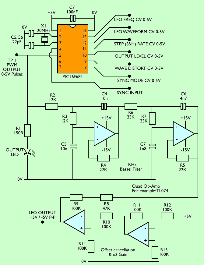
PIC16F684 Voltage Controlled LFO
Contents
LFO Control section is based on PIC16F684. However, it has many features. For a start, it can generate 7 basic waveforms and includes a noise source. In addition, beyond the basic PWM, it can morph waveforms under CV control.

There is an optional sample hold and hold module that can sample the current waveform or noise source from the selected one. LFO frequency, waveform selection, waveform distortion and S&H ratio are voltage controlled using 0-5V. The general output level is also voltage controlled.
It uses analog inputs of PIC16F684 for CVs. These are fed to the internal A / D converter, which samples each input of 150uS or more and converts the voltage to an 8-bit value. To avoid using an external D / A converter for output, the internal PWM module is used. The PWM output must pass through a low-pass filter to convert pulses back to analog output.
PIC16F18313 Single shot Generator
Here’s something a little different! LFO? An envelope manufacturer? Well, there’s a little bit of both. It generates a one-off event like an envelope generator, but has more diverse waves like the LFO.
It works by generating a single “ping” when triggered. Ping is like a small envelope. The speed and waveform of this ping are variable (55 ms to 2.5 seconds and eight different shapes), and the single ping can be increased by adding linear echoes “echoes”. There are controls for the delay (between 0 and 2.2 seconds) and the number of repetitions (between 1 and 36) for echoes.
Note that depending on Rate CV and Delay CV, these shapes may take several hundred milliseconds or more than ten seconds. The longest event that the chip can produce takes more than two minutes to complete and ends in 55 ms as soon as possible!
PIC16F688 MIDI clock for analog door beats
How do you synchronize your modular synth with MIDI equipment? It provides MIDI clock message, but you need something to turn it into a format that an analog modular synthesis can understand. Most MIDI-CV converters do the job, but this can be expensive. Here’s a cheap way to do this.
The circuit converts MIDI clock signals to 0-5V analog pulses. It provides two separate analog clock outputs that can be set in various split rates of MIDI clock; this will allow crazy politmic turmoil if you have two independent sorters. It also generates short 0-5V pulses for MIDI Start, Stop, and Resume messages, and provides a high ‘Running’ output while the MIDI clock is running. These signals can be used to control your analog circuits.
PIC16F684 Voltage Controlled Loop Generator
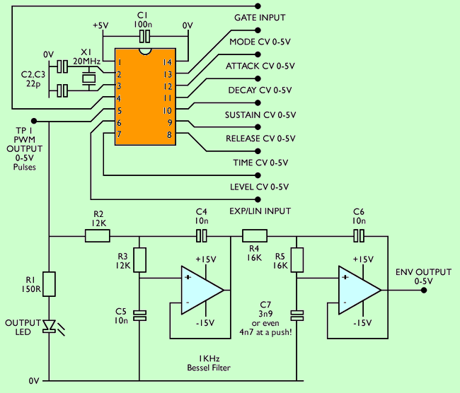
This project is an advanced version of the previous VCADSR envelope generator. While the circuit has both GATE and TRIGGER inputs, it replaces the TRIGGER input with a MOD CV that allows the selection of normal ADSR, Gated loop or full LFO-style Loop modes.
The standard ADSR mode creates the shape you expect and provides CV control of envelope depth and total time.
Gated loop mode loops while the gate is high. When the door is lowered, the envelope goes to the Release stage.
LFO Loop mode always goes into the loop, acting like a versatile LFO.
PIC16F1778 Variable ratio drum experiments with sample playback
There was a discussion about how the first digital drum machines such as LinnDrum or Oberheim DMX were used to change the pitch of drum sounds simply by changing the sampling rate. They literally played the samples faster or slower, such as speeding up or slowing down a tape recording exactly. At that time, this was pretty easy because each drum sound had its own DAC and its own sampling rate clock, and if you wanted it could be a VCO. This variable sampling rate is an important feature of many early digital hardware – PPG synthesis and Prophet VS used the same trick – and formed most of the “crunchy” or “sandy” character of these instruments. Another important element of these older digital drum machines was that they used 8-bit samples, but as far as I discovered it wasn’t what it looked like.
I was inspired by the idea of the drum machine sound and I wondered if the 1980s drum samples could be played using PIC.
I used one of my last favorite microcontrollers, PIC16F1778. It has an integrated 16K program memory, but it is more important to have three 10-bit DACs. It makes it really fun to generate signals like LFOs or envelopes… or drums!
Besides the three DACs, 16F1778 also has three 16-bit timers so they can be used to generate the required sampling hours.
My first step was to try and find some of the original 8-bit samples for some of these machines. Oberheim DMX EEPROM registers were used. Many of the examples were 4K, so I can fit three of them in my 16K program memory and there is still a lot of free space (four kilobytes!) Left for the code.
DSPIC33FJ64GP802 4 Seconds Digital Delay
Recently, I have been working on a four-second digital delay with tap tempo and delay traces. There are already many digital delay projects, but most of them are based on PT2399, which limits both the length of the delay and the sound quality.
A short summary of the features:
0 → 4 Digital delay seconds
12 bit / 32KHz input, 16 bit / 32KHz output
Delay tracks (tails) open / closed
Input / output bypass switching effect
Momentary / latching feature in bypass switch for “reverb jump”
Tap the tempo
Tempo LED shows echo rate
Dry sound path is completely analog
Delay Time, Repeats and Delay Level checks
High and Low tone filter controls
This project is based on the dsPIC 33FJ64GP802 microcontroller with 23LC1024 1Mbit / 128KB serial RAM for storage. DsPIC includes a 12-bit ADC and a 16-bit DAC. The first sampling is done at 12-bit resolution and 32KHz, but after that, the entire internal process is 16-bit, and the final output is actually 16-bit / 32KHz. 12-bit / 32 KHz is typical for the 1980’s rack studio delay processor. Super clean or non-sterile sound quality is very good. It is definitely better than PT2399 and will not be of bad quality as delays get longer.
The worst (only) problem is the background feeling. DsPIC’s DAC on the chip sounds about 10mV. Some of this is removed by post DAC filtering, but approximately 5mV remains. This is pretty noisy by modern standards. For guitar level signals, changing the four resistance values significantly increases the S / N ratio.
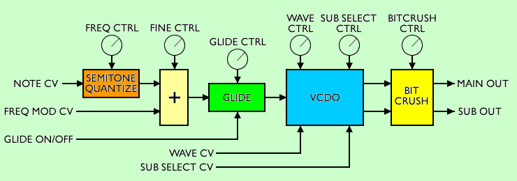
PIC16F1847 Voltage controlled digital oscillator VCDO1
A single chip 1V / Oct voltage controlled digital oscillator with 20 waveforms in a scannable wave table.
VCDO uses a PIC 16F1847 microprocessor to create a versatile and simple voltage-controlled 8-bit digital wave oscillator. All oscillator parameters are controlled with 0-5V control voltages. The chip has a natural exponential control response and makes the interface very simple, even without an exponential converter, with 1V / Oct control voltages.
Source: electricdruid.net/category/projects/
FILE DOWNLOAD LINK LIST (in TXT format): LINKS-26286a.zip


Projets d’électronique audio de synthétiseur de microcontrôleur PIC
Synthétiseur, pédales d’effet guitare Flanger etc. Bien que divers projets soient généralement des circuits avec génération de signal de synthétiseur, il existe différents projets. Tous les projets ont des descriptions détaillées de l’assemblage source et des codes hexadécimaux.
En traduction, «Générateurs d’enveloppe» signifie turc comme «générateur d’enveloppe». Je ne sais pas si la traduction n’est pas correcte;
Les générateurs d’enveloppe sont des circuits qui produisent un signal profilé dans le temps lorsqu’ils sont déclenchés, également appelé générateur de transitoires ou de contours.
PIC16F684 LFO à tension contrôlée
La section de contrôle du LFO est basée sur PIC16F684. Cependant, il possède de nombreuses fonctionnalités. Pour commencer, il peut générer 7 formes d’onde de base et comprend une source de bruit. De plus, au-delà du PWM de base, il peut transformer des formes d’onde sous contrôle CV.