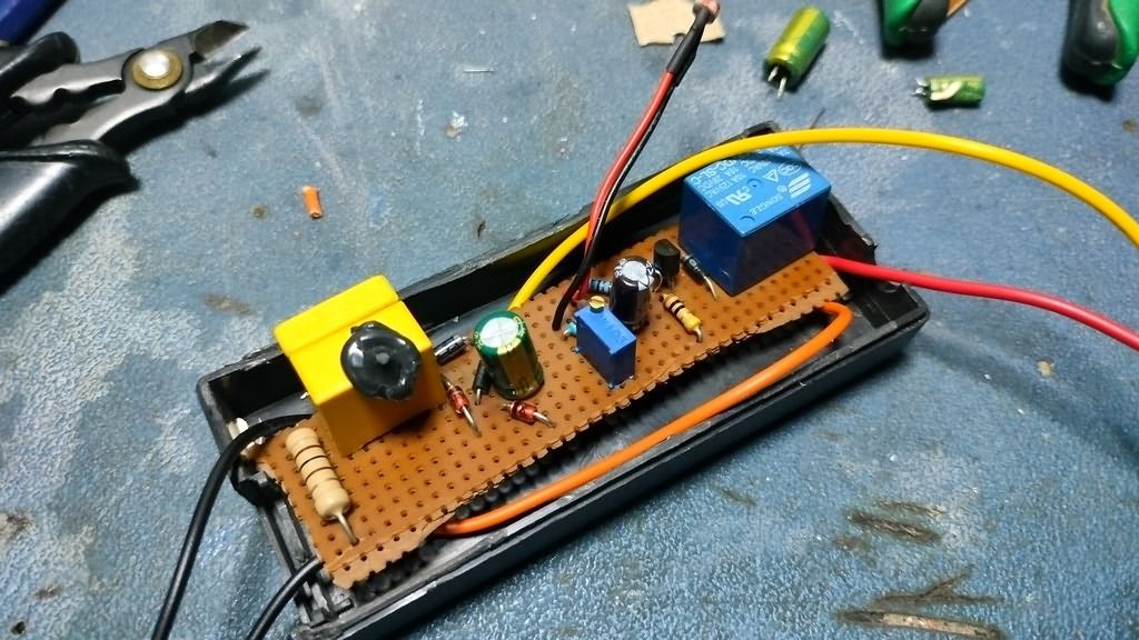
Automatic Lighting On/Off Circuit at Twilight. A device was needed for the LED lamps my friend connected in the garden, one that would apply voltage in the dark and cut it in daylight. We looked at an electrician’s shop but could not find one. They all recommend sensor lamps 🙂 Anyway, I quickly built a simple circuit, and it works well.
The 12V relay I used in the Day Night Automatic Lighting circuit draws approximately 25mA.
I operated it with a transformerless regulated circuit instead of a 12V transformer power supply or SMPS adapter.
The circuit I shared in the Transformerless Power Supply 220VAC 12VDC 100mA article was used.
For a relay drawing 25mA, the capacitor at the 220V voltage input should be 680nF 2X 275V AC. If the relay draws higher current, you can select it according to the table below.
Transformerless Power Supply Circuit Schematic
Contents
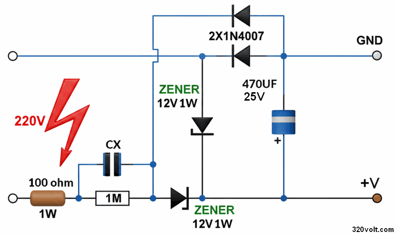
Note: For 25mA, a 680nF CX capacitor was used
| Relay Current | Calculated CX | Practical CX Selection | 100Ω Series Resistor | Zener (12V) | Filter Capacitor |
|---|---|---|---|---|---|
| 10mA | 272nF | 330nF X2 | 1W is sufficient | 1W is sufficient | 470µF / 16V is sufficient |
| 15mA | 408nF | 470nF X2 | 1W is sufficient | 1W is sufficient | 470µF / 16V is sufficient |
| 20mA | 544nF | 560nF X2 | 1W is sufficient | 1W is sufficient | 470µF / 16V is sufficient |
| 30mA | 816nF | 820nF X2 | 1W is sufficient | 1W is sufficient | 470–680µF recommended |
| 35mA | 952nF | 1µF X2 | 1W works, 2W runs cooler | 1W is sufficient, 2W is better | 470–1000µF |
| 40mA | 1088nF | 1.2µF X2 | 2W recommended | 1W works, 2W recommended | 680–1000µF |
| 45mA | 1224nF | 1.2µF X2 (at the limit), 1.5µF X2 is safer | 2W recommended | 2W recommended | 1000µF / 25V recommended |
Notes:
- For long service life, the CX capacitor must definitely be selected as X2 class.
- 1/4W is sufficient for the 1M discharge resistor.
- 1N4007 diodes can be used in the same way within this current range.
- In applications of 40mA and above, choosing 2W for the 100Ω resistor and 2W for the zener is safer.
- This circuit operates without isolation. The output side may also be dangerous with respect to the mains.
- Using 680–1000µF instead of 470µF reduces relay chatter.
- A 16V electrolytic capacitor works, but 25V is better for long service life.
This circuit, which energizes the relay when the ambient light decreases and releases the output when daylight appears, is a practical twilight switch that can be used in applications such as garden lighting, display window lighting, house number lamps, and similar uses.
In addition to being simple, the good side of the circuit is that it works with simple components and can reduce unnecessary relay triggering during short-term light changes.
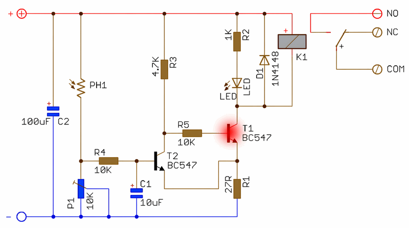
Dark Light Switch LDR Relay Circuit Schematic
Technical Specifications of the Circuit
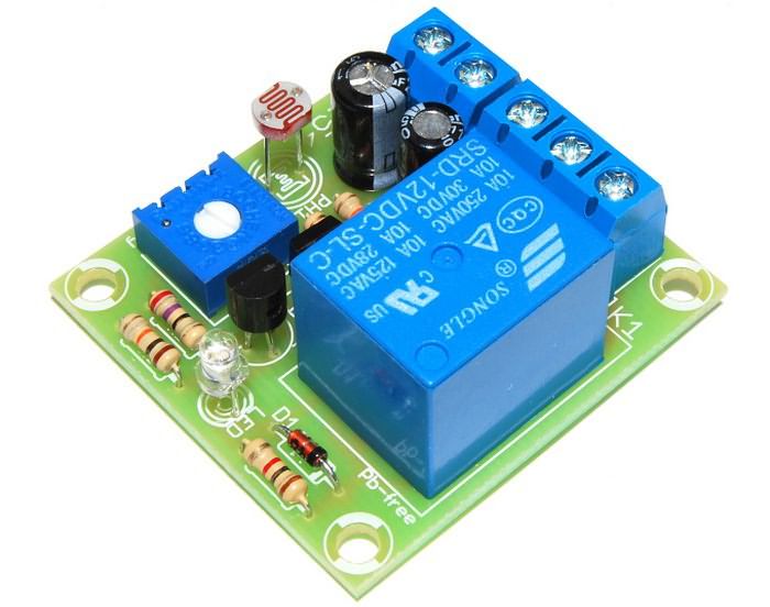
- A photoresistor is used as the light sensor
- There is a fine-adjustment potentiometer for sensitivity adjustment
- It includes a hysteresis circuit for stable operation
- It provides protection against sudden light changes
- Operating status is indicated with an LED
- The relay output supports NO or NC connection
- Supply voltage: 12V DC
- Maximum current consumption: 40 mA
- PCB size: 38 x 41 mm
How does the circuit work?
In the schematic, the light sensing task is assigned to the PH1 photoresistor. PH1 and the P1 10K potentiometer together form the detection threshold.
When the environment is bright, the resistance of PH1 decreases, T2 BC547 approaches conduction, and driving of T1 BC547 is suppressed.
When the environment becomes dark, the PH1 resistance increases, T2 goes into cutoff, and T1 turns on through R3 and R5, energizing the K1 relay (SRD-12VDC-SL-C).
Light sensing and delay section
The R4 10K and C1 10uF combination smooths sudden changes at the sensor point.
Thus, the possibility of the circuit unnecessarily switching on and off due to effects such as lightning, vehicle headlights, or short-term flashes is reduced.
The activation threshold can be adjusted with the P1 trimpot.
The source document says that the circuit includes both “protection against short-term light changes” and “hysteresis”; in the schematic, C1=10uF, R4=10K, R5=10K, R1=27R, and T1-T2 BC547 are seen as the components that can provide this.
1) Slowing against momentary light flashes
When lightning, a car headlight, or a short flash occurs, the resistance of the photoresistor changes suddenly. But this change does not go directly and instantly to the base of T2. Because the signal coming through R4 progresses by charging and discharging the C1 capacitor. In other words, C1 acts here as a small “delay / filtering” element.
The logic is this:
Even if the light changes suddenly,
the voltage at the T2 base cannot change at the same speed.
The voltage rises and falls over some time.
If the change lasts very briefly, the event ends before the relay threshold is exceeded.
So this section actually behaves like a simple RC low-pass filter.
2) Preventing rapid on-off chattering near the threshold
This is the hysteresis section. Once the relay pulls in or releases, the new state of the circuit slightly changes the next decision threshold. Thus, exactly at the limit:
it got a little dark and pulled in,
it got a little bright and released,
pulled in again,
released again
continuous chattering like this does not occur. In the schematic, T1-T2, R5, and R1 on the common emitter line create this together. When the relay state changes, the operating point of the transistors shifts slightly; in other words, the turn-on and turn-off threshold does not remain at the same point.
The main part that suppresses momentary flashes: C1 10uF
The path that creates this delay: R4 + sensor network + C1
The hysteresis section that reduces chattering: around T1, T2, R5 and R1
Relay drive and indicator section
T1 BC547 is the relay drive transistor. The K1 relay is energized by being pulled to ground through T1.
R2 1K and LED are used as the operating indicator. The D1 diode provides protection against reverse voltage pulses from the relay coil.
R1 27R and the two-transistor structure also contribute to more stable switching behavior near the threshold level.

Connection and adjustment information
- The supply is applied as 12V DC to the + and – terminals on the board.
- If the load is desired to turn on in the dark, COM and NO terminals are used.
- If the load is desired to turn on in daylight, COM and NC terminals are used.
- The light level at which the circuit will operate is adjusted by slowly turning the P1 trimpot.
- The photoresistor should be placed so that it does not directly see the light of the controlled lamp itself.
Things to pay attention to
- If 230V AC will be used on the relay contact side, connections must be made with power off, and the entire system must be operated inside a closed plastic box.
- In the source design, the total current consumption of the board is approximately 40mA. Therefore, selecting a 45mA relay should be considered close to the limit value.
- The LED used as the indicator may leak light to the sensor in some boxes. In such a case, the LED should be moved to a different point or not used if necessary.
- The transformerless power supply is not isolated. Therefore, the low voltage side is not independent from the mains either. Be careful.
Similar Circuits
For those who want to see different circuits on the same subject, the article about transistorized dark-activated circuits with LDR sensors can be examined.
For those looking for an op-amp-based alternative solution, the 741 op-amp 12V dark switch article is useful.
If light control together with motion detection is desired, the HC-SR501 PIR sensor LED lamp application will also be useful.
This circuit, built with two BC547s, one LDR, a few resistors, and a 12V relay, offers a low-cost, adjustable, and practical twilight switch solution.
With correct relay selection, sensor placement, and safe power supply use, it can be used without problems in garden, display window, signboard, and decorative lighting applications.
PCB Drawings
The first drawing was copied from the original document with Sprint Layout 6. The drawings were checked but not tested.

Source: arlisklep.pl/files/ARLI/AR154.pdf