The fan speed control circuit is a simple MOSFET regulator that automatically adjusts the rotational speed of a 12V DC fan using an NTC temperature sensor. It is suitable for hobbyists and technical service applications that want to reduce unnecessary fan noise in power supplies, amplifiers, PC cases, or battery-backed devices.
Main Purpose of the Circuit
Contents
- 1 Main Purpose of the Circuit
- 2 Fan Control Circuit Schematic and Block Structure
- 3 Component List and Functions
- 4 Connection Method
- 5 Placement of the NTC Sensor
- 6 LED and D1 Protection Diode
- 7 Technical Summary
- 8 First Startup and Adjustment
- 9 Common Mistakes
- 10 Which Fans Is It More Suitable For?
- 11 Application Examples
- 12 Limits of the Circuit
- 13 Assembly Notes
Fans are often operated at full speed; although this method seems safe in terms of cooling, it causes unnecessary noise, excessive current consumption, and mechanical wear.
The circuit is a simple solution that increases the fan speed smoothly according to temperature.
At low temperature, the circuit rotates the fan slowly. As the ambient temperature or heatsink surface warms up, the resistance of the NTC thermistor changes, the MOSFET conducts more, and the fan voltage increases.
Thus, the fan reaches high speed only when needed.
This structure is especially useful for power supplies, audio amplifiers, regulator boxes, battery charger circuits, and enclosed electronic housings that use 12V DC fans.
Fan Control Circuit Schematic and Block Structure
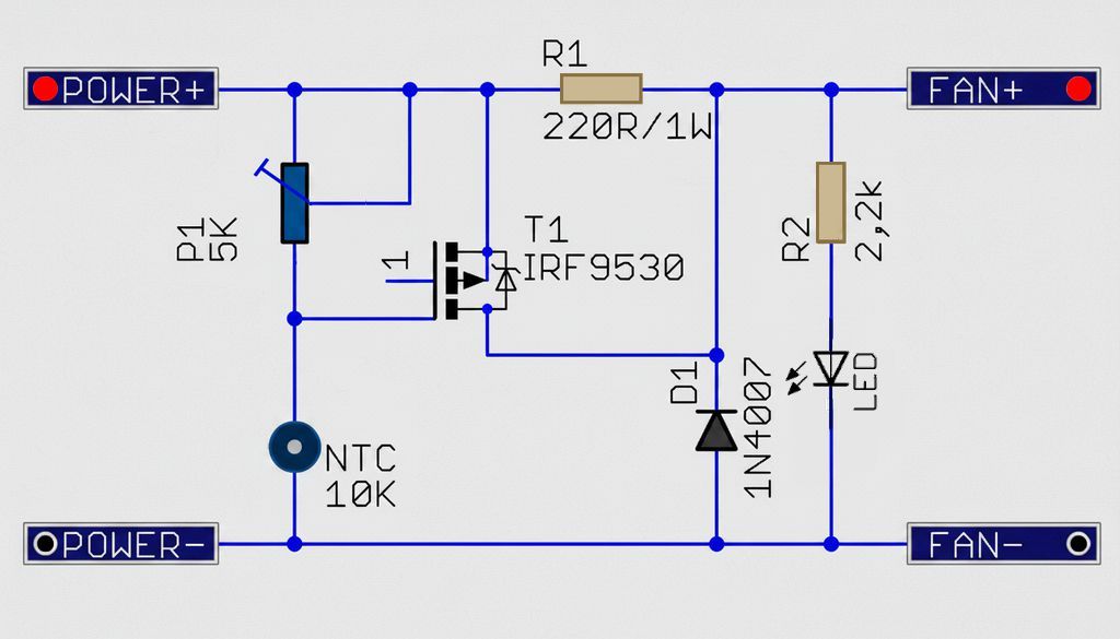
The schematic consists of four main sections: the temperature sensing section, MOSFET control stage, fan output, and indicator-protection components.
At the center of the circuit is the T1 IRF9530 P-channel MOSFET. The NTC and P1 potentiometer determine the MOSFET gate voltage.
The R1 resistor creates a limited supply path that prevents the fan from stopping completely at low temperature.
Temperature Sensing Section
The NTC 10K thermistor is used as the temperature sensor. In an NTC-type thermistor, resistance decreases as temperature increases.
In the schematic, the NTC works like a voltage divider together with the P1 potentiometer and changes the voltage at the gate terminal of the T1 MOSFET.
In a cold environment, the NTC resistance remains high. In this case, the MOSFET gate voltage is closer to the positive rail, and the MOSFET operates with weak conduction or close to cutoff.
When the temperature increases, the NTC resistance decreases, the gate voltage is pulled down, and the P-channel MOSFET conducts more strongly.
Sensitivity Adjustment with the P1 Potentiometer
The P1 5K potentiometer is used to adjust the temperature level at which the fan starts to speed up.
Since the potentiometer determines how strongly the gate node is connected to the positive supply, the threshold point created by the effect of the NTC changes.
If it is not desired for the fan to immediately reach full speed during adjustment, the potentiometer should be turned slowly and the fan behavior should be observed for a few seconds.
The response may not be instant due to the thermal mass of the NTC and the surface where it is located.
MOSFET Power Stage
T1 IRF9530 is a P-channel MOSFET that operates on the positive line of the fan.
This connection type can be considered high-side control.
When the MOSFET conducts, the limited path created by the R1 resistor is largely bypassed and the fan receives a higher voltage.
The circuit is not a classic PWM control. The fan voltage changes in an analog manner.
Therefore, the MOSFET may heat up in the linear conduction region. As the fan current increases, the power dissipated on the MOSFET also increases.
For fans of 1A and above, the MOSFET temperature must be checked, and a small heatsink should be used if necessary.
Low-Speed Path with R1
The R1 220Ω/1W resistor is connected from the positive supply to the FAN+ line. Even when the MOSFET is fully off, the fan can receive limited current through this resistor.
In this way, the fan can continue rotating at low speed, or at least the output line does not remain completely floating.
The R1 value can become critical depending on the fan type. While low-current 12V fans may rotate slowly through this resistor, high-current fans may only vibrate slightly or may not start at all.
If the value is reduced, the fan speed at low temperature increases; however, the resistor power rating must also be increased.
In a near-short-circuit condition, the power that may occur on R1 should be evaluated using approximately the V²/R calculation.
Component List and Functions
| Reference | Value / Model | Function in the Circuit |
|---|---|---|
| R1 | 220Ω / 1W | Creates a low-speed supply path for the fan and limits the current when the MOSFET is off. |
| R2 | 2.2K | Limits the LED current. |
| P1 | 5K potentiometer | Adjusts the temperature sensitivity and the fan speed-up threshold. |
| NTC | 10K thermistor | Affects the MOSFET gate voltage by changing resistance according to temperature. |
| T1 | IRF9530 | Controls the fan supply as a P-channel MOSFET. |
| D1 | 1N4007 | Provides protection against reverse voltage spikes that may come from the fan motor. |
| LED | Standard LED | Indicates that voltage is present at the fan output. |
Connection Method
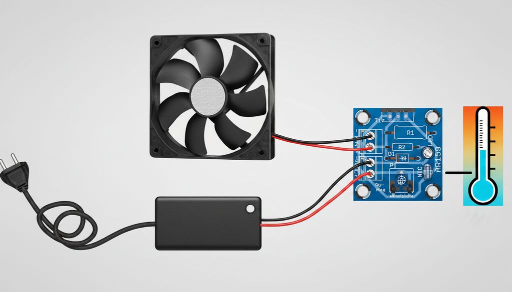
There are two main connection points in the circuit. A 12V DC supply is connected to the POWER+ and POWER- terminals. The 12V DC fan is connected to the FAN+ and FAN- terminals.
- The red wire of the fan is connected to the FAN+ terminal.
- The black wire of the fan is connected to the FAN- terminal.
- The positive supply terminal is connected to the POWER+ connection.
- The negative supply terminal is connected to the POWER- connection.
- The NTC sensor is placed close to the surface whose temperature will be monitored.
The safest method for the first test is to use a current-limited laboratory power supply. If a power supply is not available, adding a fuse with a suitable value to the supply line helps protect the MOSFET and the fan in case of an incorrect connection.
Placement of the NTC Sensor
If the NTC sensor is left freely in the air, the circuit responds to ambient temperature. If a heatsink block, transformer, power resistor, or regulator body will be monitored, the NTC should be fixed in thermal contact with that surface.
The sensor can be extended with a cable; however, mechanical strength and noise effects should be considered with long cables.
If the cable is very long, using a twisted pair and avoiding routing the sensor line near a powerful motor or SMPS transformer provides more stable results.
If the NTC will be attached to a metal surface, care should be taken to prevent its leads from short-circuiting. Heat-resistant heat-shrink tubing or thin insulating tape can be a practical solution.
If thermal contact is poor, the fan responds late; this may cause unwanted temperature rise, especially in power transistor or regulator cooling applications.
LED and D1 Protection Diode
R2 and the LED are added to visually monitor the voltage at the fan output. When the fan is at low speed, the LED may glow dimly, and as the MOSFET conducts, the brightness may increase. The LED should not be considered a precise voltmeter here; it only indicates that the output is active.
The D1 1N4007 diode is used to suppress reverse voltage spikes that may result from the inductive structure of the fan motor.
Although these spikes often do not create a major problem in small DC fans, a protection diode is the right choice for longer MOSFET service life.
Technical Summary
| Feature | Value / Description |
|---|---|
| Supply voltage | 12V DC |
| Control type | Analog fan speed control with NTC temperature sensing |
| Fan current | Can be used up to approximately 1.5A |
| Output power | Suitable for fan loads of approximately 20W |
| Temperature adjustment | Sensitivity adjustment with the P1 potentiometer |
| Sensor | 10K NTC thermistor |
| Power component | IRF9530 P-channel MOSFET |
| PCB size | Approximately 28 x 29 mm |
First Startup and Adjustment
After assembly is complete, 12V is applied to the circuit while the fan is connected. It is safe to start with the potentiometer set to the middle position.
When the NTC is at room temperature, the fan should rotate at low speed or move very slowly depending on the fan used.
When the NTC is heated with a finger or brought close to a hot surface, the fan speed should increase.
If the fan does not speed up, the NTC connection, P1 solder joints, and MOSFET orientation should be checked first.
If the fan continuously operates at full speed, the gate line may be connected incorrectly, the NTC may be short-circuited, or the MOSFET may be damaged.
During adjustment, the initial startup behavior of the fan should also be observed. Some fans cannot start rotating at low voltage but operate when given a manual push.
When used with such a fan, the R1 value or control curve should be re-evaluated according to the application.
Common Mistakes
- Reversing the supply polarity: The MOSFET, LED, and fan may be damaged. The POWER+ and POWER- terminals should not be energized without checking them.
- Placing the NTC in the wrong location: If the sensor remains far from the heat source, the fan speeds up late.
- Using a high-current fan without a heatsink: The MOSFET may heat up in linear conduction. The package temperature should be checked during long-term testing.
- Connecting a 4-wire PWM fan with the wrong expectation: The circuit changes the supply voltage of the fan; it does not generate a motherboard-type PWM control signal.
- Randomly reducing the R1 value: The fan rotates faster at low temperature, but the power dissipated on the resistor increases.
Which Fans Is It More Suitable For?
The circuit is most easily used with standard two-wire 12V DC fans. In three-wire fans, the red and black supply wires can be used; the yellow tachometer wire is not required for this circuit. In four-wire PWM fans, the fan supply can also be controlled, but this method does not mean driving the actual PWM input of the fan.
Low-current fans with quality bearings rotate more stably at low voltage. Some cheap or high-current fans may stall at low voltage.
In devices requiring critical cooling, it must be tested that the fan starts reliably at every temperature.
Application Examples
- Increasing fan speed according to heatsink block temperature in a linear power supply
- Increasing fan speed when output transistors heat up in an audio amplifier
- Monitoring the temperature of the transformer or diode heatsink in an SMPS box
- Increasing airflow during high charging current in a battery charger
- Reducing continuous fan noise in small electronic housings
Limits of the Circuit
The circuit is a simple and practical fan control circuit; however, thermostatic or microcontroller-based PWM solutions may be more accurate for systems where precise temperature regulation is expected. In this circuit, the temperature-fan speed relationship depends on the NTC, potentiometer, MOSFET characteristics, and the behavior of the fan used.
If the fan current approaches the 1.5A limit, MOSFET cooling should not be neglected. For larger fans, parallel fan groups, or 24V systems, the circuit should not be scaled up directly; the MOSFET, resistor power rating, diode, and supply limits should be recalculated.
Assembly Notes
- Low-profile components such as resistors and diodes should be soldered first, followed by the potentiometer, terminal block, and MOSFET.
- If the D1 diode is installed in reverse, it may load the output line close to a short circuit.
- If the LED orientation is wrong, the indicator will not work; fan control may still operate.
- The MOSFET pinout should be checked according to the PCB layout.
- Leaving no flux residue on the gate line after soldering provides more stable operation.
This fan control circuit built around the NTC and IRF9530 is a practical solution for applications that require temperature-dependent cooling with a low component count.
Thanks to R1, the fan is not completely cut off abruptly at low temperature; as the temperature increases, the output power rises through the MOSFET.
Correct NTC placement, suitable fan selection, and monitoring the MOSFET temperature are the three most important points for reliable operation of the circuit.
Source: arlisklep.pl/files/ARLI/AR159.pdf