@Bülent NUR forwarded by my teacher PCB spark gap videosu review, especially in power electronics PCB designs contains useful information for possible leakages on the system high voltage spark gap for a method to be applied to minimize damage thanks @Bulent
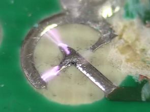
Spark gap
A spark gap consists of an arrangement of two conducting electrodes separated by a gap usually filled with a gas such as air, designed to allow an electric spark to pass between the conductors. When the voltage difference between the conductors exceeds the breakdown voltage of the gas within the gap, a spark forms, ionizing the gas and drastically reducing its electrical resistance. An electric current then flows until the path of ionized gas is broken or the current reduces below a minimum value called the “holding current”. This usually happens when the voltage drops, but in some cases occurs when the heated gas rises, stretching out and then breaking the filament of ionized gas. Usually, the action of ionizing the gas is violent and disruptive, often leading to sound (ranging from a snap for a spark plug to thunder for a lightning discharge), light and heat.
Spark gaps were used historically in early electrical equipment, such as spark gap radio transmitters, electrostatic machines, and X-ray machines. Their most widespread use today is in spark plugs to ignite the fuel in internal combustion engines, but they are also used in lightning arresters and other devices to protect electrical equipment from high-voltage transients.


Electronic Dice Circuit With PIC12F629
the PIC12F629 on a microcontroller based electronic dice. electronic DICE with 14 LEDs dual membranes prepared for application software mikroc used to give random results when a button is pressed for 3 seconds if not used within 15 seconds after it goes to sleep mode normal operation of the circuit of the button continues. Electronic DICE circuit PCB Sprint layout prepared with ISIS simulation software source code that belong to the file and drawing.
Electronic Dice circuit
Leiterplatte-Funkenstrecke
Eine Funkenstrecke besteht aus einer Anordnung von zwei leitenden Elektroden durch eine Lücke getrennt, in der Regel gefüllt mit einem gas, wie Luft, entworfen, um zu ermöglichen, einen elektrischen Funken zwischen den Leitern. Wenn die Spannungsdifferenz zwischen den Leitern überschreitet der Durchbruchspannung von der gas-in die Lücke, ein Funke bildet, ionisierende gas und drastisch verringert den elektrischen Widerstand. Ein elektrischer Strom dann fließt, bis der Pfad von ionisiertem gas defekt ist oder der Strom reduziert, die unterhalb einer minimum-Wert namens “holding current”. Dies geschieht meist, wenn die Spannung sinkt, aber in einigen Fällen tritt auf, wenn das erhitzte gas steigt, stretching und brechen das filament von ionisiertem gas. In der Regel, die Wirkung von ionisierenden gas ist heftig und störend, was Häufig zu sound hin snap für eine Zündkerze nach thunder für eine Blitz-Entladung), Licht und Wärme.