
The TDA7377 amplifier circuit is one of the projects I implemented years ago. The TDA7377 integrated circuit is used in many audio systems because it provides various output combinations, is inexpensive, and requires very few components.
I last used it in my desktop arcade speaker project.

While reviewing my arcade speaker archive, I realized I forgot to share this 🙂 I’m sharing it as a separate post. The TDA7377 can provide 4 separate outputs. For building a 2.1 amp, 2 outputs are used normally, and the other two are bridged. Music power is 2x 15W right and left outputs, and 30W bass output. The frequency response of the stereo outputs is approximately 100 Hz to 20,000 Hz.
The PCB layout for the circuit was created using Sprint Layout 6; its dimensions are 60mm x 60mm, single-layer.
TDA7377 2+1 Amplifier Circuit Diagram
Contents

TL072 Preamplifier
The TL072 contains two amplifiers, interchangeable with the JRC4558, TL082, or NE5532. Each has its own characteristic sound.
The function of the TL072 op-amp IC in the amplifier is to amplify the signal, since the TDA7377 has a fixed and somewhat low gain.
For example, if we amplify an audio signal from a mobile phone directly with the TDA7377, the sound will be low. However, by first passing it through the TL072 preamplifier, the sound will be louder.
Furthermore, we can simply change the gain by changing a few resistors.
The gain is set to 10. This is found by dividing the 56K resistor by the 5.6K resistor. For example, if we want to increase the gain, we can increase the value of the 56K resistors.
If the goal is to reduce the gain, and the output of the audio source is very strong and distorted, it will be sufficient to decrease the value of the same resistors.
TL081 Low-Pass Filter (Bass Filter)
The subwoofer low-pass filter receives the amplified signal from the TL072 for processing.
The low-pass bass filter restricts the passage of high and mid-frequencies, allowing only low frequencies to pass through.
The TL081 is an integrated circuit containing only a single amplifier.
Frequency reduction is primarily provided by two 0.47 uF capacitors connected in parallel between the input and output of the TL081.
If you need more frequency reduction, simply increase the value of these two capacitors. The bass response of the TL081 is better than that of the TL071.
TDA7377 Power Supply
The TDA7377 amplifier integrated circuit operates with a single DC voltage source. Its operating voltage is between 8VDC and 18VDC; performance is poor at 8V, the ideal operating voltage is between 12V and 15V.
There is no DC rectifier circuit on the PCB. If you are considering using a transformer, you must first use a DC rectifier. The transformer voltage can be 12VAC.
If you have a ready-made DC adapter, you can connect directly. The TDA7377 can draw high instantaneous current; the power supply should have a power of 5 amps or more.
Which speakers should we use?
The power rating of a speaker should be equal to or slightly higher than the output power of the amplifier.
Each stereo output should be 15W, and the speakers should be able to handle 15W RMS or more.
Full-range speakers are recommended. Since bass is separate, another option is to use speakers with good mid and high response.
Size is a matter of personal preference. Tested with 2.5-inch speakers and 5.5-inch, 2-way car speakers.
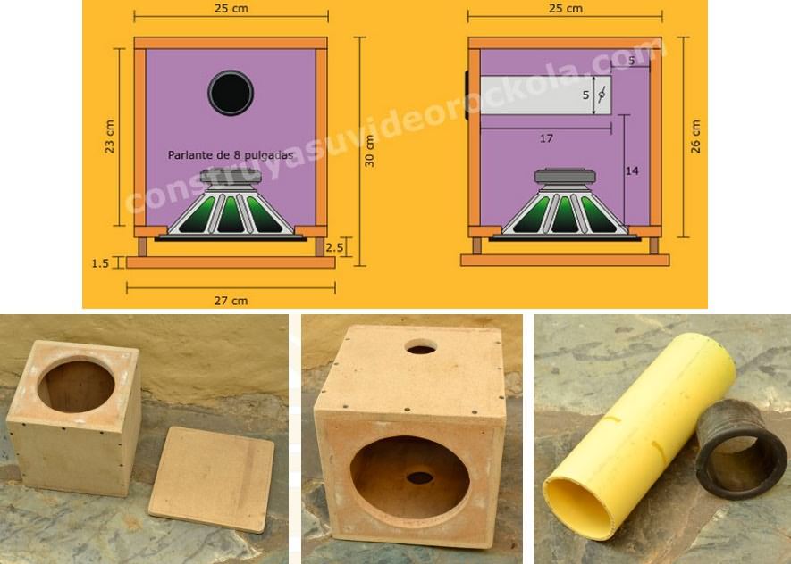
For bass, you should use a subwoofer with 30W RMS or more power. A size between 6 and 8 inches is recommended.
Good Sounding Subwoofer Cabinet Drawing
About the TDA7377 PCB Printed Circuit Board

About the TDA7377 PCB Printed Circuit Board: The PCB layout for the TDA7377 2+1 Amplifier project was prepared using Sprint Layout 6.
A single-layer PCB design was created. This will make prototype PCB manufacturing easier.
If you wish to order from a China-based PCB manufacturing company, the Gerber and source code drawings for PCB production are included in the file.

TDA7377 Test Video
This is my Desktop Arcade Cabinet project using the TDA7377 2.1 Amplifier circuit.
source: construyasuvideorockola.com


