Lamp Flasher Circuit NE555 integrated control of 220 volt mains supply for over-current through the resistor capacitor and so on. taken with passive elements so no need to use a transformer to supply RV1 and RV2 brightness of the lamp flashing speed can adjust the lamp power used to control the triac (bt136 bt139 available) moc3031 drive is controlled by isolated
CAUTION Be careful is working with high voltage capacitor circuit connections Beware + – If you connect the high voltage polarity may be large explosions before running the insured Power Line circuit, protective goggles
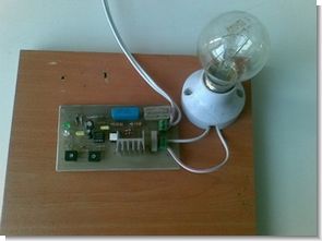
Lamp Flasher Circuit Diagram , Completed Photo


Lamp Flasher Circuit Test
Lamp Flasher Circuit 555 Proteus isis schematic PCB files
Transformerless 220V Lamp Flasher Circuit 555 ZIP File Password: 320volt.com


Amateur Radio SSB VFO PLL Transceiver Receiver Circuits
And the other part, and use the 9MHz crystal filter, and switch the crystal oscillation of the carrier, the upper – – Zener has been let out also -, Ro~ua. MIC AMP is, making the DSB is placed in the ring modulators 1N60 4 pieces, the AF signal of 0.5V was used for about 40dB amplify the OP AMP 741 I make through the SSB filter is amplified by AMP of 2SK241. The filter, diode received – detected by the 1N60 amplified in two stages 2SK241 by fart the de SW, spin in the LM386 – sounds mosquitoes.
a 14MHz The MIX in the SN76514, the signal from the signal of 5MHz
14MHz SSB transceiver