The generator section uses a 9MHz crystal filter, and for carrier oscillation, the crystal can be switched to remove both the upper and lower frequencies.
I was … The MIC AMP uses the OP AMP 741, amplifying it by about 40 dB and inserting the 0.5 V AF signal into four 1N60 ring modulators to create a DSB. Boost with 2SK241’s AMP and filter SSB. Also for reception go through filter and diode switch, boost with 2SK241 and then boost with 1N60.
Loud speaker with detection and LM386. The 14MHz converter section mixes the signal from the generator and the 5MHz level signal from the Mizuho VFO-5 with the SN76514 to create 14MHz. Use the last power amplifier 2SC1971 to make 5W. After RF amplification is made with 2SK241 in the receiver converter section, the signal converted to 9MHz by mixing with the VFO signal with 3SK77 is sent to the generator section. The ANT switch part consists of a T-type filter, a relay, and a transistor SW.
14MHz SSB transceiver
50MHz SSB transceiver
144MHz PLL FM receiver
5MHz PLL VFO
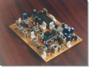
14MHz5W SSB transceiver
DBM module
Digital display 14MHz SSB transceiver
14MHz SSB transceiver
Contents

50MHz SSB transceiver
As you can see from the block diagram, transceivers very ordinary output of 250mW. SSB generator part, was to use one of the available 14MHz transceiver made earlier. It is the configuration of the power supply unit from the substrate and a total of two. In order to 250mW, the output from the generator part, requires amplification of about 34 ~ 44dB by taking into account the attenuation of the DBM because it is about-10dBm about. I made in the amplifier stage two of the original 2SC2053 2SC1906, but was increased by one step output shortage, the FET2SK241
144MHz PLL FM receiver
I tried to make the 144MHz band FM receiver using PLL VFO. The device, MC3359, PLL circuit is orthodox with MC145163 in 2SK241, IF to RF. 75 × 50 and the 50, PLL 75 ×, I made a substrate Sunhayato of 10K (70 × 100) a receiving unit to compact this time. I use it without cutting because it is convenient all the time if I one piece board.
5MHz PLL VFO
You are using the VFO-5 of Mizuho now, but you would use the considerable effort and suffer from QRH When it comes to own this. PLL VFO A developed this time, you can make changes at 1KHz step the range of 5 ~ 5.5MHz use the MC145163. It is inconvenient at 1KHz step but as that you get together the frequency to the other party first I tried to own in SSB
14MHz5W SSB transceiver
tried to make 14MHzSSB transceiver output 5W using the 2SC1171 in the final (transverter part). Is converted to 14MHz is placed in a MIX of the DBM made with ferrite bead FB801, a signal of SSB of 9MHz from the generator unit made last time, 2SC1171 is amplified by AMP three-stage 2SK241, 2SC1906, 2SC2053
DBM module
Because I use the DBM fine to radio production, I tried to modularize a small board. Pay in-black BLK-300 of Sunhayato, also look better if Katamere to this. You can compact more I used the FB801 to the core, but if I use the quad diode to diode also, the FB101 Digital display 14MHz SSB transceiver
Source: web1.incl.ne.jp Amateur Radio SSB VFO PLL Transceiver Receiver Circuits schematic PCB alternative link:


PIC16F88 Digital Voltmeter Circuit
Voltmeter circuit PIC16F88 microcontroller C language prepared by the program based on the indicators used for the 7-segment LED display with integrated TTL 74ls47 74hc238 and are driven. pic16F88 of AD was made using a digital voltmeter conversion. The goal is practical resolution of about 10mV maximum voltmeter that can measure up to 20V. AD is also in practice, so use a conversion 7 seg. indicator will ignore the practical value for the five-digit minutes.