
Analog industrial transmission standards are still in use, as evidenced by the wide range of sensors available on the market. Existing systems sometimes require maintenance or expansion with new sensors.
A lower-cost implementation compared to the previously shared project “AD694JNZ 0.10V 4.20mA 0.5V 4.20mA Converter Circuit”
4-20mA 0-10V Converter Parameters:
Conversion of 4-20mA current to 0-10V DC voltage
Simple calibration
Output resistance: 100Ω
Option to adapt the output to the 0-5V standard
Power supply: 15-32V DC, typically 24VDC
Current consumption: approximately 20mA.
Current-to-voltage conversion is most easily accomplished using a simple resistor, and Ohm’s law does the rest. Unfortunately, with a standard 4-20 mA current loop and a typical output load resistance of 250Ω, we obtain a DC voltage ranging from 1 to 5V. This range is not fully compatible with the 0-5V standard, or the more popular 0-10V standard in industrial applications, because it does not utilize the full operating range offered by the ADC at the PLC input.
Therefore, a simple resistor divider will be sufficient to linearly convert the 4-20 mA current loop output to a 0-10V voltage input! But that’s not all, as swapping the two resistors will also allow this circuit to operate at the 0-5V standard.
4-20mA 0-10V Converter Circuit Diagram

The current flowing from the current loop transmitter flows through the terminals of connector J1 and resistor R1, causing a voltage drop there; this is then low-pass filtered by a simple circuit consisting of resistor R2 and capacitor C1.
The pre-filtered DC voltage in the 1-5 V range must be shifted and amplified to the 0-10 V range. This is achieved using a non-inverting amplifier based on the LM358 opamp. In this amplifier, the non-inverting input is biased with a potential derived from a voltage divider consisting of resistors R3 and R4. The gain of this amplifier is determined by resistor R5 and the combined output resistance of the divider R3+R4. Capacitor C2 limits the amplifier’s bandwidth, reducing the effective noise voltage at the output. Resistor R6, connected in series with the output of the LM358 operational amplifier, is designed to prevent excitation when driving a high-capacitance load, such as a long shielded cable.
In addition to creating a low-pass filter, resistor R2 also compensates for the current feeding the base of the input transistor in the LM358 amplifier. The net resistance of the circuit powering the inverting input is 4 kΩ. The non-inverting input, on the other hand, sees resistors R1 and R2 connected in series because the internal resistance of the current source (current loop emitter) is very high. Theoretically, the resistance of R2 should be 3751 Ω, but a value of 3.9 kΩ in series would be a good approximation.
A 5 V reference voltage is required for the amplifier described above to operate correctly. Here, the popular LM317 regulator is used in a circuit that allows for small-range output voltage adjustment using a multi-turn potentiometer. This allows for a 5 V voltage regardless of changes in resistor values or the reference voltage source incorporated into the LM317 circuit. Furthermore, a slightly higher current can be drawn from the output of this regulator, which is beneficial for powering the entire circuit. Capacitor C7 reduces output voltage ripple by improving the ripple ratio (PSRR).
The LM358 can theoretically operate with an asymmetric power supply, but achieving zero output voltage is problematic. A simple negative voltage generator has been added to the circuit to improve the device’s performance at low output voltages. The well-known and popular NE555 integrated circuit operates as an astable generator with an output pulse duty cycle of approximately 50%. Thanks to its maximum 18VDC supply voltage, it is powered by the regulator described earlier. The output of this timer controls a simple diode-capacitor voltage inverter that provides an output voltage of approximately -3V. While this isn’t a significant difference, it is sufficient to improve the LM358’s performance at low output drive levels.
The LM358 chip contains two operational amplifiers. The second unused amplifier is connected as a voltage follower, whose input is biased by the 5V potential from the regulator output. Theoretically, it would be possible to implement an astable generator using this without using the additional NE555 IC, but this would lead to two problems:
First, this circuit is self-powered, as the negative voltage it generates would be applied to the circuit’s own negative supply line, which could cause problems with generator excitation.
Second, pulses generated in one part of the silicon structure could penetrate into the adjacent part implementing the voltage amplifier. Therefore, it was decided to use a completely separate IC to implement the negative voltage supply, even at the cost of a small expansion of the circuit.

During startup, the 5V reference voltage must be set using potentiometer P1. Connect power to connector J3; this should be a DC voltage in the range of 15-32V, well filtered from fluctuations but not necessarily regulated.
You can use 24V, which is commonly used to power PLCs and sensors. The lower limit of the allowable supply voltage is due to the need to ensure proper operation of the LM358 operational amplifier’s output stage at a 10V output voltage, while the maximum limit is due to the durability of the components.
After powering up the system, connect a voltmeter with the highest possible sensitivity between the system ground (GND) and the PAD1 solder pad and adjust potentiometer P1 so that the voltage indicated by the voltmeter is 5V.
This affects the error in subsequent current-to-voltage conversion, so the more accurately this step is performed, the better the system’s subsequent operation.
A properly configured circuit is ready for operation. The input of the circuit is connector J1, to which the current loop transmitter output should be connected. A voltage is present at the J2 connector terminals that linearly represents the input current (with an appropriate offset): 0V corresponds to a current of 4mA, and 10V corresponds to a current of 20mA. If the input current is less than 4mA (for example, after the current loop is opened), the output voltage will be negative but will not fall below approximately -2V. In this case, output resistor R6 can limit the current flowing through the input protection diodes of the next stage.
An output resistance of slightly more than 100Ω should be considered when making connections, as if the input resistance of the circuit measuring this voltage is too low, an erroneous result can be obtained. Typical PLCs have an input resistance of 100kΩ, so resistor R6 will cause a negligible error here; the error due to normal component scattering will be larger. However, resistor R6 should also be considered when creating the voltage divider.
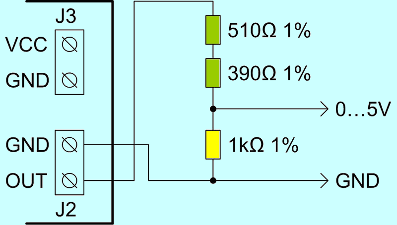
To ensure compliance with the 0.5V standard, the recommended component values ensure a voltage division equal to 2, as the upper arm of this divider contains resistors with a total resistance 100Ω less than the lower arm.
The output resistance of such a device is 500Ω, which is sufficient for most applications, such as connecting to the input of a microcontroller’s analog-to-digital converter. Another modification can be made to this circuit. To ensure that the voltage output varies within the 0.5V range, simply replace resistors R3 and R4 with 30kΩ resistors with a 1% tolerance. The output resistance will then remain at 100Ω.
Example of connecting a voltage divider to achieve a 0.5V output voltage range:
The LM317 integrated circuit does not require a heatsink. Its maximum power dissipation should not exceed approximately 0.5 W, and a TO220 package can accommodate this value. In cases where the circuit is enclosed in a tight, airtight enclosure, it is beneficial to solder this regulator to longer pins and attach a heatsink to it; in such cases, a metal part alone may not be sufficient. This is especially true when operating at higher supply voltages, such as 24 V or higher.
Source: ep.com.pl/projekty/projekty-ep/16447-konwerter-4-20-ma-na-0-10-v


