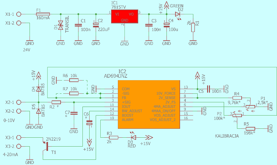
Voltage-Current converter circuit AD694JN integrated circuit based on the circuit, fed through the 7815 regulator input voltage can be 18-35 VDC. The minimum value of the power supply for 0-10V is 12.5V.
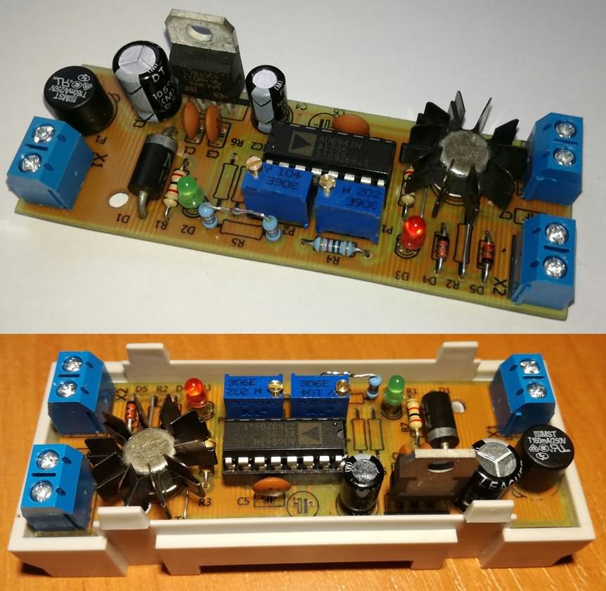
The “4mA” value in the uncalibrated model was 4.18mA. The values given in the diagram are taken from the catalog note, 2k potentiometers and 1% tolerance resistors 10k and 200k are used in the model. T1 transistor is used to minimize the error caused by the heating of AD694JN. In the prototype, BC211 supported with a small heatsink is used. Diode D3 indicates the current loop is open.
To use resistors R6, R7 of 10k, it is sufficient to disconnect between pins 1 and 2 of AD694JN. This way you get 2 wins.
AD694JNZ Converter 0-10V – 4-20mA or 0-5V – 4-20mA circuit diagram;
Eagle cad pcb and schematic files of AD694JNZ 0.10V 4.20mA 0.5V 4.20mA converter circuit; 28450a.zip password: 320volt.com