There a few years, PC began to be powerful enough to réaliserde software synthesis. For my part, I discovered the real time software synthesis with ReBirth on my Pentium 166MHz MMX. Of course, software synthesis exist on the PC, such as Virtual Waves, but the arrival of real-time creates a turning point for me anyway. At the same time, he created a new need.
A few years ago, PCs began to be powerful enough to perform software synthesis. For myself, I discovered real-time software synthesis with ReBirth on my Pentium 166MHz MMX. Of course, PC had synthesis software like Virtual Waves, but the arrival of real time was a turning point, at least for me. But it also created a new need.
Using parameters in ‘live’ is not easy with the mouse. So the solutions were to use other midi compatible instruments to control the synthesis software. But if you’ve experimented this way, you’ve definitely noticed the problems it introduces… Controls are often not suited to the use you want to use them for, not to mention the affected potentiometers are almost always on demand. to enable the parallel use of these machines.
Based on these observations, I embarked on the construction of an autonomous midi controller called the OPAZ, without waiting for several years for manufacturers to need it and dedicate a few products. Of course that’s what happened, and now (28/10/2003) we find this kind of product on the market.
The project was original back then, less so now, but it’s an easily adaptable project that might interest you if you’re thinking of implementing a custom/custom MIDI control desk.
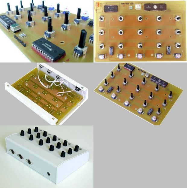
What’s more, when there’s almost nothing in electronics… and the design is relatively simple, it always amuses me to see what price manufacturers of such equipment are displaying their products at. The cost of my little prototype by no means exceeds 800 francs (yes, pennies of the time 😉 or about 120 euros to be modern 🙂 Of course, the prototype cost me much more to work and design, but if you get the prototype as it is, for the whole (components, box, connectors, etc.) plate, offset etc.) 120 Euro is a good guess.
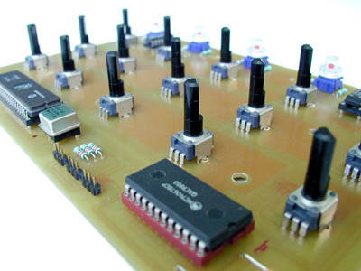
The main purpose is to provide MIDI signals based on 15 rotary knobs. More precisely, the potentiometers of the rotary knobs 15 will be scanned by a multiplexer controlled by a Microchip PIC16C77 microcontroller, which itself will also take care of the AD conversion. As soon as it finishes converting to digital, it compares the obtained value with the old value it keeps in its memory, and if this has changed (ie the potentiometer has been rotated) it transmits a new one. MIDI protocol.
Three bytes are then transferred (channel number and ‘Control Change’ type – controller number – controller value). Now for the main lines. Actually the program is a bit more complex, for example I use a small anti-oscillation routine based on subtraction (and switching from 8 bits to 7 bits), which prevents saturation of the midi channel due to timeless transmission of a value, or the last bit is sometimes 1, sometimes 0′. readable converter. Likewise, I use a controller number reassignment routine that simplifies the design of the IC. However, I recommend that you look at the resources for more information.
The second purpose is to send midi commands (note, control…) using the 5 switch/leds located at the bottom of the console, and to position the led according to a midi data from another place. . To perform these operations, two chips are used – a multiplexer and a state memory – 74HC4051 and 74HC259. Unfortunately, I never finished the software implementation of these functions… Beware of amateurs!
Source: m.bareille.free.fr PIC17C77 Midi Control Circuit MC14067 alternative link:


0-30V DC Voltage Current Power Monitor
DC POWER SUPPLY CONTROL SYSTEM 0-30V DC output capable circuit protected power supply to the crash the pursuit of power is a system which can be installed simply. Since the output voltage does not interfere with the regulation of the power supply can be used with all kinds. The system can be screened simultaneously in four separate measurements.
they are:
DC voltage value
The current value
Resistive load impedance
Load power (Watts)