LM324 Electronic Load 4 Mosfet is the 8 mosfet version of the LM324 op amp blind load device shared in the article. The PCB size is 10x10cm and single-layer. The circuit is made of the same driver stage and combined in 2 pieces and controlled from a single point via TL431.
According to my previous experiences, the insulators we use to isolate the mosfets from the aluminum heatsink in electronic load circuits cause a big problem in heat transfer. I did not use an insulator in this project, in this case there is a positive + voltage on the heatsink, I will have to be more careful and make a plastic box.
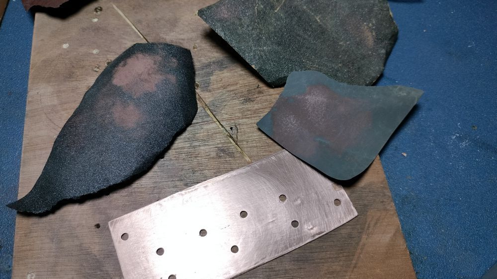
As you can see, I used small ready-made coolers for the first test. In addition, I mounted a copper plate on the coolers. The coolers got quite hot in the 30V 20A test, but the heat of the mosfets was not excessive, in other words, the heat of the mosfets is quickly transferred to the cooler as I wanted. I will add a larger, thicker single piece cooler and a 15cm fan and box it. I am thinking about various protections, indicators (50A) etc.
In the previous circuit I used a large cooler and 2 fans but the front body of the mosfet was getting very hot at high current, meaning the heat was not transferred fast enough, I overcame this problem
First test 30V 20A
Electronic Load Circuit Diagram

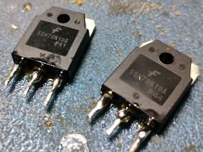
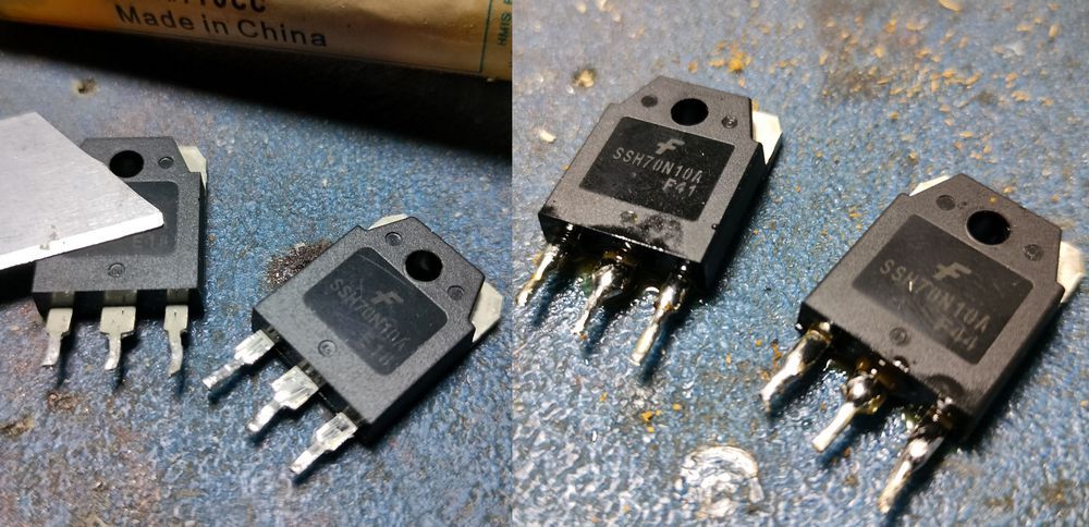
Since I use a mosfet in the blind load circuit, I extend the legs with 1.5mm wire and use it to strengthen the legs. Pay attention to this, if you are going to work with high power, solder additional wires to the legs of the mosfets. I will most likely mount it horizontally on the cooler again, when the mosfet transistors are mounted vertically on the cooler, the cooler area at the bottom is less.
Finally, I thought I was the first to think of it 😀 but the kits of this double structure have already been made and its power is stated as 600W. I will publish an article or video when the boxing etc. is finished…


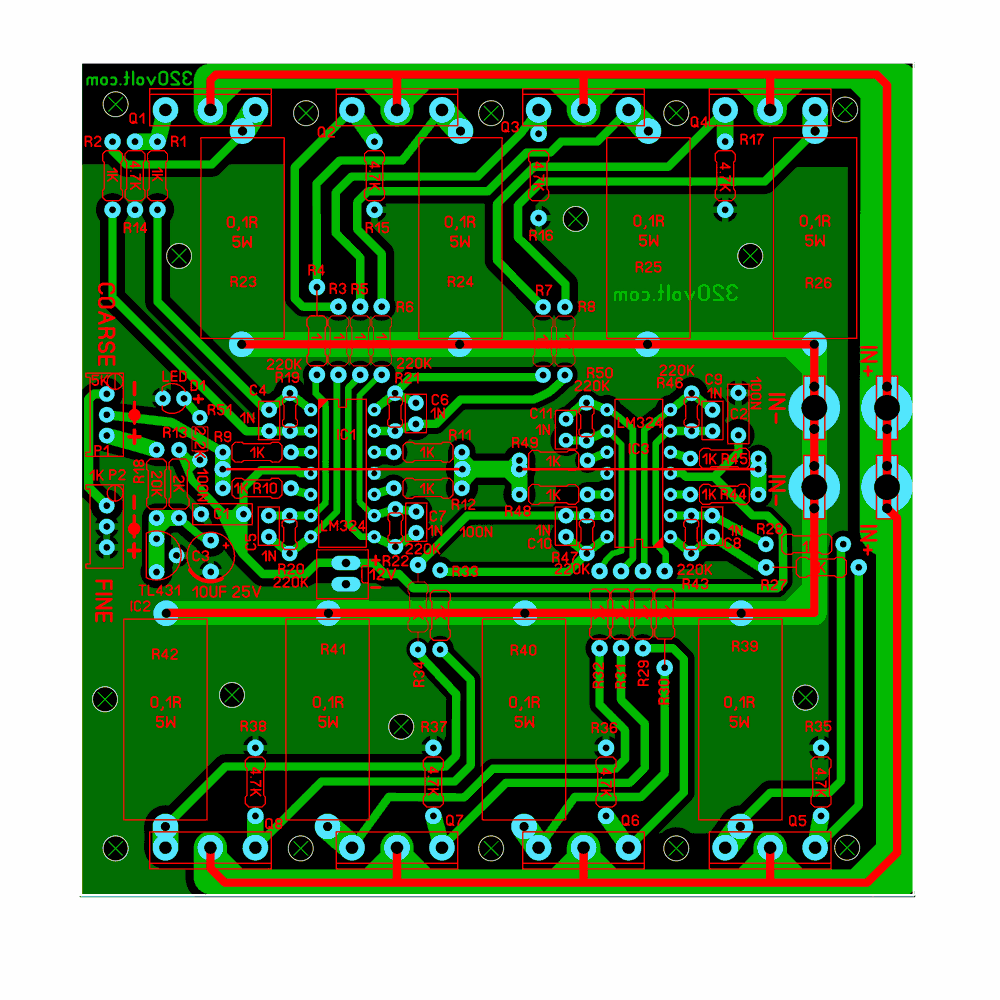
600W Electronic Load Circuit PCB drawing


