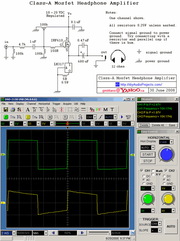
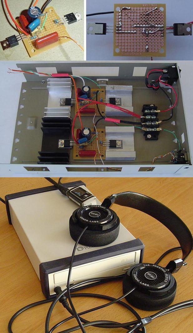
A simple headphone amplifier circuit 32Ω headphones ideal for basic elements 1 mosfet (IRF610) and the positive regulator (LM317) crating CD-ROM Box used circuit 10 .20 volts dc voltage is working with 750mA current draw hole pertinaks on does not look good but after boxed pretty stylish stands
DIY ClassA Head phone Amplifier Circuit
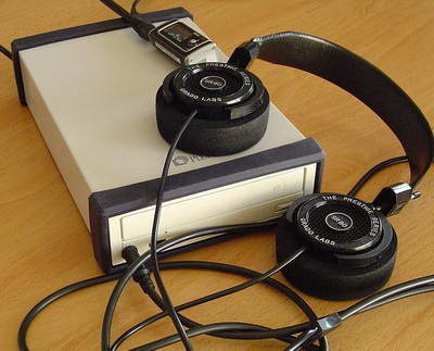
Not thrilled with how a computer soundcard drove my 32 ohm Grado SR80 headphones, I decided to build myself a desktop headphone amplifier for the office. As with most of my projects, the goal was to keep it simple, keep cost down and try use some salvaged part
There are a couple of items to note. A FET follower circuit will be able to supply high current, but the voltage gain will be less than one. This amplifier will only be suitable in applications where the input signal does not require voltage amplification (such as the output of an mp3 player or computer). Also, a simple single-ended circuit like this will have no power supply ripple rejection and thus any noise in the power supply is going to go right through amplifier. For that reason, you will need to use a regulated power supply. Suitable inexpensive regulated (wall wart) power supplies can be purchased from Radio Shack. 10-20VDC and 750mA should be fine.
Source: diyaudioprojects.com/ Class A Headphone Amplifier with LM317 and IRF610 Mosfet alternative link:


Electric Bike Motor Control Circuit TC4420 PWM PIC16F819
Motor control circuit PWM method used PIC16F819 output microchip product tc4420 high speed 6 amp mosfet driver used MOSFETs, the two pieces irf2907 also switched MOSFETs current drawn to detect tlv2461 op amp made with 0.01ohm shunt resistor current through the sensing circuit there. PWM motor driver pcb project’s source code pic-c, schematic files.