Driving a car into the garage after dark can be fatal if it has no lighting. The presented system automatically switches on the lighting, without leaving the vehicle. He will also remember to turn them off later.
The switch system is designed for 230V AC supply. It works by detecting a beam of light (coming from passing, position or stop lights) incident on the photoresistor.
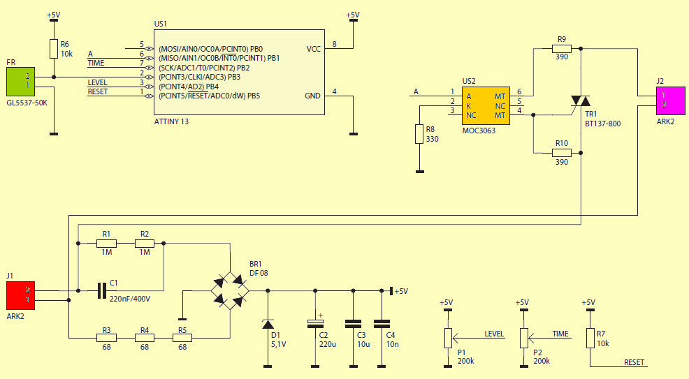
The ATtiny13 microcontroller is responsible for all system functions. Every 4 ms it reads the voltage on the photoresistor and on the potentiometers P1 and P2 using A / C. The potentiometer P1 is the set threshold, and the potentiometer P2 is responsible for setting the activation time.
If the photosensitive element is not illuminated and the voltage on it is higher than on the P1 potentiometer slide, the output remains inactive. Otherwise, the load is switched on via the triac. The optotriac was not used here to achieve galvanic separation, but to properly control the triac gate using a small current.
The switch-on time is adjustable in steps of one second, in the range from approx. 10 s to approx. 18 minutes. The setting of the P2 potentiometer used to determine the switch-on time is checked on an ongoing basis during the countdown, therefore it is possible to make corrections easily. After counting down the set time, the system turns off the load and unconditionally waits 3 seconds. Such a delay is necessary because lamps illuminating the room would arouse the system and it would never turn them off.
The transformerless power supply is designed to supply 5 V. The resistors R1 and R2 discharge the capacitor C1 after power off, and R3 … R5 reduce current surges when power is turned on. In addition, if the capacitor C1 breaks down, one of the resistors R3 … R5 will act as a fuse and break the circuit. The voltage straightened with a Graetz bridge is stabilized by a Zener diode.
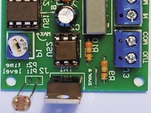
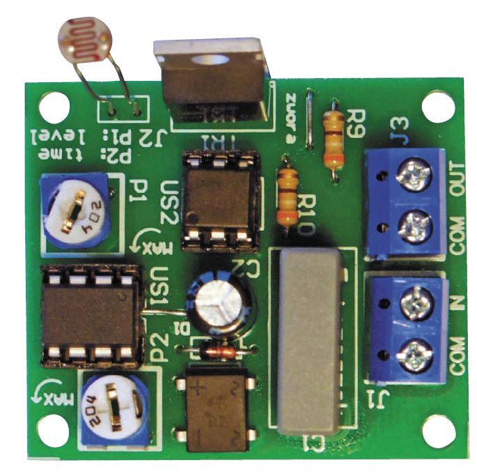
The switch arrangement is mounted on a single-sided printed circuit board, the assembly diagram of which is shown in Figure 2. The dimensions of the switch allow it to be mounted in a 60 mm diameter electrical box. Installation should begin with soldering the elements in SMD housings. Then all threaded components are soldered. It is good to use bases for integrated circuits.
The security bits in the ATtiny13 microcontroller should be left at the factory, except for the CKDIV8 bit, which must be deactivated. The photoresistor leads should be soldered to the terminals marked FR. The photoresistor itself should be placed opposite the car’s lights so that it can be illuminated. The type of photoresistor is any, but its electrical parameters must be similar to the GL5537 used in the prototype:
resistance in the dark 2 MΩ,
resistance at 10 lx lighting: 20 … 50 kΩ,
resistance at 100 lx lighting: 4 … 10 kΩ.
The triac used in the prototype allows you to switch on loads that consume no more than 8 A, but above about 0.5 A, it is advisable to mount the triac on a heat sink. In addition, for currents exceeding 3 A, thickening of the paths is recommended. Due to the specifics of the Triac operation, the controlled load should be selected so that the current consumption is not less than approx. 30 mA
The adjustment operations to be carried out are uncomplicated: after correct connection, set the potentiometer P1 in half and P2 on the minimum. First, the adjustment is made with the P1 potentiometer until optimal sensitivity is found. Turning the slide towards the “MAX” direction decreases sensitivity, i.e. stronger lighting is required to operate. When the response threshold is satisfactory, there is an extension of burn time.
Since all components on the circuit board have a galvanic connection to the electrical network, it is essential to comply with the safety rules during startup and operation of this system.
Lighting switch circuit schematic
![]()
FILE DOWNLOAD LINK LIST (in TXT format): LINKS-26485a.zip


Interrupteur d’éclairage dans le garage
Conduire une voiture dans le garage après la tombée de la nuit peut être fatal si elle n’a pas d’éclairage. Le système présenté allume automatiquement l’éclairage, sans quitter le véhicule. Il se souviendra également de les désactiver ultérieurement.
Le système de commutation est conçu pour une alimentation 230V AC. Il fonctionne en détectant un faisceau de lumière (provenant des feux de croisement, de position ou d’arrêt) incident sur la photorésistance.
Le microcontrôleur ATtiny13 est responsable de toutes les fonctions du système. Toutes les 4 ms, il lit la tension sur la photorésistance et sur les potentiomètres P1 et P2 en utilisant A / C. Le potentiomètre P1 est le seuil réglé et le potentiomètre P2 est responsable du réglage du temps d’activation.
Si l’élément photosensible n’est pas éclairé et que la tension sur celui-ci est supérieure à celle du curseur du potentiomètre P1, la sortie reste inactive. Sinon, la charge est activée via le triac. L’optotriac n’a pas été utilisé ici pour réaliser une séparation galvanique, mais pour contrôler correctement la grille du triac en utilisant un petit courant.
Le temps de mise en marche est réglable par pas d’une seconde, dans la plage d’env. 10 s à env. 18 minutes. Le réglage du potentiomètre P2 utilisé pour déterminer le temps de mise en marche est vérifié en permanence pendant le compte à rebours, il est donc possible de faire des corrections facilement. Après le décompte du temps réglé, le système arrête la charge et attend inconditionnellement 3 secondes. Un tel délai est nécessaire car des lampes éclairant la pièce réveilleraient le système et ne les éteindraient jamais.