During the past year, I replaced a lot of batteries at home with a lot of batteries and replaced them with Li-ion batteries. Lantern radios, Led lantern, Hand broom etc …
One of the radio lanterns was a 6v battery and the other one was a 1.5v pen pile. One of the two Li-ion batteries was enough battery power for the Li-ion battery + strike tip serial 1n4007 diode connected to 0.7v voltage loss I made a simple rule with the problem did not make a problem ..
Led flashlight 6v battery 1 Li-ion battery is enough Bleached batteries 3 serial Ni Mh batteries connected 3.6v in it 2 Li-ion pliers connected in parallel
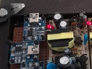
The mini SOT-23-5 I use for the radio and led flashlight charging circuits is able to power 500mA on the MCP73831 is used with an external circuit element. I used the 5V adapter as the power source for the circuits I put into the devices
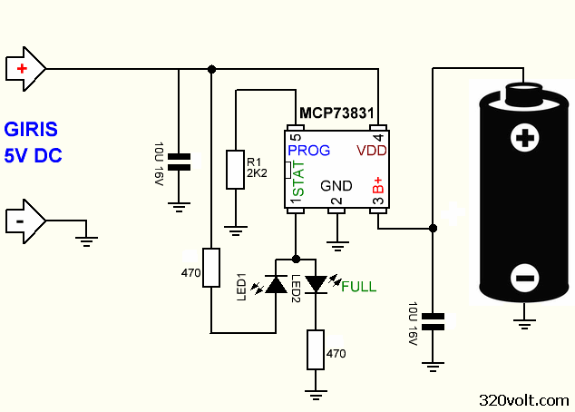
I also placed the bubble charging circuit in the adapter when the vacuum cleaner is running, if the MCP73831 charging circuit is connected. In the case of MCP73831 R1 resistor is used for current setting, I use 2.2K, 500mA 2K, 240MA 4.2K, 160MA 6.34K, 130MA 7.87K, 100MA 10K capacitors in 10K input and output will be poleless.
MCP73831 Li-ion Battery Charging Circuit Diagram
Contents
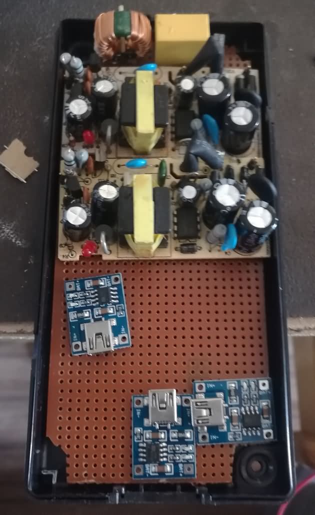
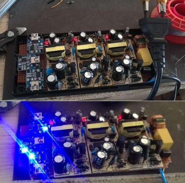
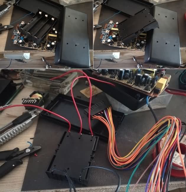
I needed to use a separate power supply for each of the TP4056 modules. There were a few high power SMPS cards in the box, but it did not save them. I’ve been trying to repair a 1.6A 5V SMPS adapters and have used it on my device, but the SMPS adapters are waiting for a long corner repair. I also used the defective SMPS adapter box for boxing.
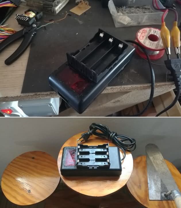
I installed the 3-Li-ion battery socket on the box and soldered the modules to the solder modules. I cut the box part of the box to see the charge status and added red mica …
TP4056 Connection
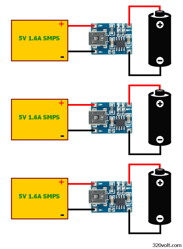
If you have a high-power SMPS adapter, you do not need to use separate power supplies for TP4056 modules.
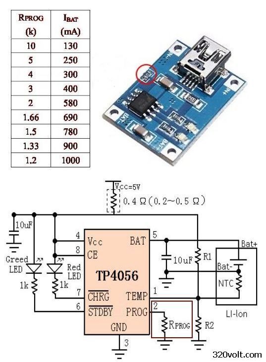
The current of the TP4056 charge integration can be adjusted. TP4056 modules are usually equipped with “Prog” resistors for the highest output current The TP4056 can be set to 130mA …. 1000mA by changing the resistor connected to Pin 2.
If the power supply in your hand is slightly above the power charging current, for example, if you use a 5V 1A adapter, you must set the TP4056 module current at your hand to 800mA or less, or your adapter may fail or go into protection.
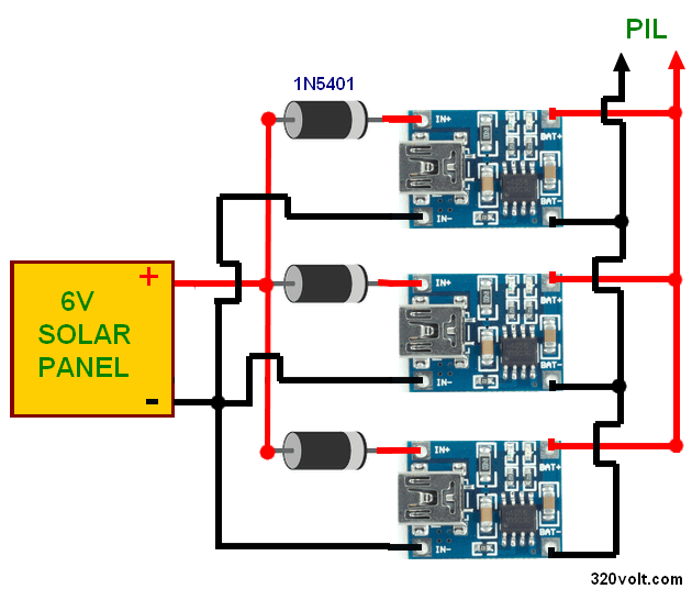
TP4056 solar panel-charger
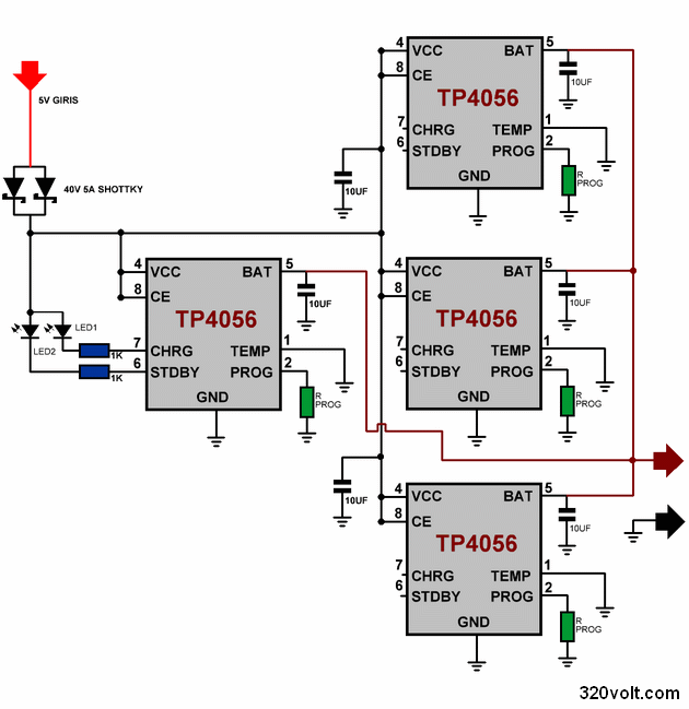
TP4056 4X Parallel Connection Schematic


Li-Po Li-Ion-Ladegerät MCP73831 TP4056 Schaltungen
Im letzten Jahr habe ich viele Batterien zuhause gegen viele Batterien ausgetauscht und durch Li-Ionen-Akkus ersetzt. Laterne Radios, Led Laterne, Handbesen etc …
Eine der Funklaternen war eine 6V-Batterie und die andere war ein 1,5-V-Stiftstapel. Eine der beiden Li-Ionen-Batterien war genug Batterieleistung für die Li-Ionen-Batterie + Streikspitze serielle 1n4007 Diode mit 0,7 V Spannungsverlust Ich machte eine einfache Regel mit dem Problem machte kein Problem ..
LED-Taschenlampe 6V Batterie 1 Li-Ionen-Akku ist genug gebleichten Batterien 3 Serien-Ni-Mh-Batterien 3,6V angeschlossen in ihm 2 Li-Ionen-Zangen parallel geschaltet
Der Mini SOT-23-5, den ich für den Radio- und LED-Blitzladekreis verwende, ist in der Lage, 500mA zu versorgen. Der MCP73831 wird mit einem externen Schaltungselement verwendet. Ich habe den 5V-Adapter als Stromquelle für die Schaltungen verwendet, die ich in die Geräte gesteckt habe
Laboratory Power Supply 0-50V 0-4A
Laboratory Power Supply 0-50V 0-4A
Laboratory Type 0-50V 0-4A Adjustable power supply circuit A classic design based on the TL081 opamp .. I think I may have misread the scheme in the electrical or electronic circuit books ..
Laboratory Power Supply Transformer used in the power supply circuit with 4 BD249 transistors on the output stage. Single output can be used 2X25VAC instead of 50VAC Transformer.
In the regulated power supply circuit, there is a much cheaper alternate ready-made module for resistive junctions to use voltmeters and ammeters built with the ICL7107 integration, and you may not use them because they are internal. In the same PCB drawing of the same circuit, these elements have been added to make an additional 3.3k potency adjustment in the unused circuit.
Applicators of the laboratory type power supply circuit did not use an insulator for the power control transistors. In the design that can not have volt-amp meter elements, the T4 BD140 transistor is connected to the refrigerant but not necessary. Since the collectors of the BD239 and BD249 transistors are combined, there is no isolator in the coolant connection, so all the coolant voltage is stored. If you use a metal case for the power supply, it may fail if it touches the chassis.
Circuits de charge de batterie Li-ion Li-Po MCP73831 TP4056
Au cours de la dernière année, j’ai remplacé beaucoup de piles à la maison par beaucoup de piles et les ai remplacées par des piles Li-ion. Radios lanternes, lanterne Led, balai à main etc…
L’une des lanternes radio était une pile de 6 V et l’autre était une pile de stylos de 1,5 V. L’une des deux batteries Li-ion était suffisamment chargée pour la batterie Li-ion + la diode série 1n4007 connectée à une perte de tension de 0,7 V J’ai fait une règle simple avec le problème n’a pas fait de problème ..
Lampe de poche LED Batterie 6v 1 batterie Li-ion est suffisante Batteries blanchies 3 batteries série Ni Mh connectées 3.6v dedans 2 pinces Li-ion connectées en parallèle
Le mini SOT-23-5 que j’utilise pour les circuits de charge de la radio et de la lampe de poche led est capable d’alimenter 500mA sur le MCP73831 est utilisé avec un élément de circuit externe. J’ai utilisé l’adaptateur 5V comme source d’alimentation pour les circuits que j’ai mis dans les appareils
J’ai également placé le circuit de charge des bulles dans l’adaptateur lorsque l’aspirateur fonctionne, si le circuit de charge MCP73831 est connecté. Dans le cas de la résistance MCP73831 R1 utilisée pour le réglage du courant, j’utilise des condensateurs 2,2K, 500mA 2K, 240MA 4,2K, 160MA 6,34K, 130MA 7,87K, 100MA 10K en entrée et sortie 10K sans polarité.
Nice circuits