Laboratory Type 0-50V 0-4A Adjustable power supply circuit A classic design based on the TL081 opamp .. I think I may have misread the scheme in the electrical or electronic circuit books ..
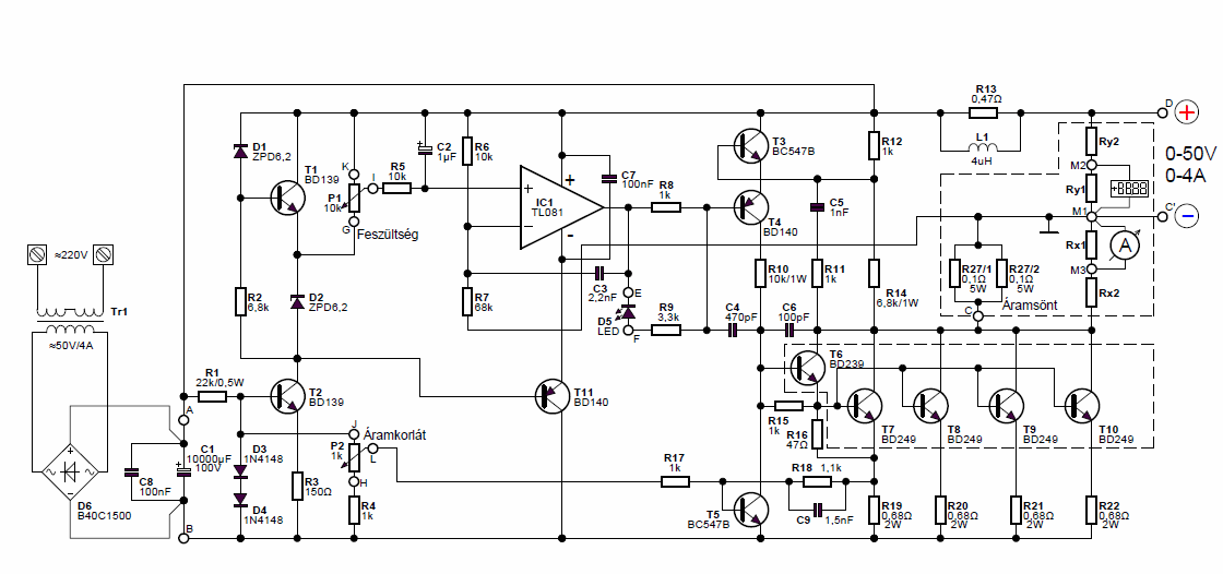
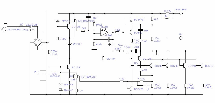
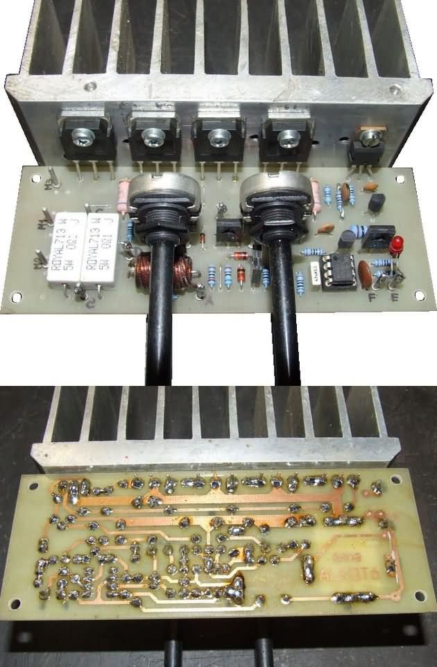
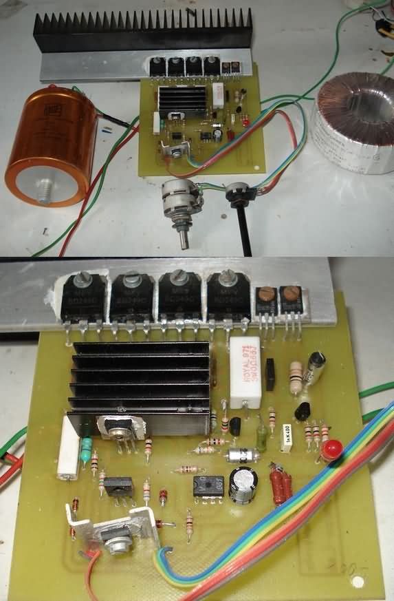
Laboratory Power Supply Transformer used in the power supply circuit with 4 BD249 transistors on the output stage. Single output can be used 2X25VAC instead of 50VAC Transformer.
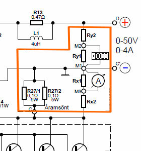
In the regulated power supply circuit, there is a much cheaper alternate ready-made module for resistive junctions to use voltmeters and ammeters built with the ICL7107 integration, and you may not use them because they are internal. In the same PCB drawing of the same circuit, these elements have been added to make an additional 3.3k potency adjustment in the unused circuit.
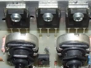
Applicators of the laboratory type power supply circuit did not use an insulator for the power control transistors. In the design that can not have volt-amp meter elements, the T4 BD140 transistor is connected to the refrigerant but not necessary. Since the collectors of the BD239 and BD249 transistors are combined, there is no isolator in the coolant connection, so all the coolant voltage is stored. If you use a metal case for the power supply, it may fail if it touches the chassis.
0.50 Volt 0.4 Amp Power Supply Circuit Schematics
source:
hobbielektronika.hu/forum/topic_1560.html?pg=127
elektro.zolee.hu/rajz_mutat.php?mutasd=75
FILE DOWNLOAD LINK LIST (in TXT format): LINKS-25942.zip


0.50V 0.4A Laborstromversorgung
Labor Typ 0-50V 0-4A Einstellbarer Stromkreis Ein klassisches Design basierend auf dem TL081 Opamp .. Ich denke, ich habe das Schema in der elektrischen oder elektronischen Schaltung Bücher falsch gelesen.
Labornetzteil Transformator, der in der Stromversorgungsschaltung mit 4 BD249-Transistoren an der Ausgangsstufe verwendet wird. Single-Ausgang kann 2X25VAC anstelle von 50VAC Transformer verwendet werden.
Im geregelten Stromversorgungsschaltkreis gibt es ein viel billigeres alternatives fertiges Modul für Widerstandskontakte, um mit der ICL7107-Integration gebaute Voltmeter und Amperemeter zu verwenden, und Sie dürfen sie nicht verwenden, weil sie intern sind. In der gleichen PCB-Zeichnung der gleichen Schaltung wurden diese Elemente hinzugefügt, um eine zusätzliche 3,3k-Potenzeinstellung in der unbenutzten Schaltung vorzunehmen.
Li-Po Li-ion Battery Charge MCP73831 TP4056 Circuits
Li-Po Li-ion Battery Charge MCP73831 TP4056 Circuits
During the past year, I replaced a lot of batteries at home with a lot of batteries and replaced them with Li-ion batteries. Lantern radios, Led lantern, Hand broom etc …
One of the radio lanterns was a 6v battery and the other one was a 1.5v pen pile. One of the two Li-ion batteries was enough battery power for the Li-ion battery + strike tip serial 1n4007 diode connected to 0.7v voltage loss I made a simple rule with the problem did not make a problem ..
Led flashlight 6v battery 1 Li-ion battery is enough Bleached batteries 3 serial Ni Mh batteries connected 3.6v in it 2 Li-ion pliers connected in parallel
The mini SOT-23-5 I use for the radio and led flashlight charging circuits is able to power 500mA on the MCP73831 is used with an external circuit element. I used the 5V adapter as the power source for the circuits I put into the devices
I also placed the bubble charging circuit in the adapter when the vacuum cleaner is running, if the MCP73831 charging circuit is connected. In the case of MCP73831 R1 resistor is used for current setting, I use 2.2K, 500mA 2K, 240MA 4.2K, 160MA 6.34K, 130MA 7.87K, 100MA 10K capacitors in 10K input and output will be poleless.
MCP73831 Li-ion Battery Charging Circuit Diagram
Alimentation de laboratoire 0-50V 0-4A
Type de laboratoire 0-50V 0-4A Circuit d’alimentation réglable Une conception classique basée sur l’opamp TL081 .. Je pense que j’ai peut-être mal lu le schéma dans les livres de circuits électriques ou électroniques ..
Transformateur d’alimentation de laboratoire utilisé dans le circuit d’alimentation avec 4 transistors BD249 sur l’étage de sortie. Une seule sortie peut être utilisée 2X25VAC au lieu de 50VAC Transformer.
Dans le circuit d’alimentation régulé, il existe un autre module prêt à l’emploi beaucoup moins cher pour les jonctions résistives pour utiliser des voltmètres et des ampèremètres construits avec l’intégration ICL7107, et vous ne pouvez pas les utiliser car ils sont internes. Dans le même schéma PCB du même circuit, ces éléments ont été ajoutés pour effectuer un ajustement de puissance supplémentaire de 3,3 k dans le circuit inutilisé.
Les applicateurs du circuit d’alimentation de type laboratoire n’utilisaient pas d’isolateur pour les transistors de commande de puissance. Dans la conception qui ne peut pas avoir d’éléments voltampères, le transistor T4 BD140 est connecté au réfrigérant mais pas nécessaire. Étant donné que les collecteurs des transistors BD239 et BD249 sont combinés, il n’y a pas d’isolateur dans la connexion du liquide de refroidissement, donc toute la tension du liquide de refroidissement est stockée. Si vous utilisez un boîtier métallique pour l’alimentation, il peut échouer s’il touche le châssis.