
Transformer Tester: After designing a microcontroller-based wide-range ring tester, the question arose whether a basic version of the Coil Tester could be designed, usable by anyone with electronics skills, using common 4000 series CMOS integrated circuits and other electronic components. This tester is the result. It’s a popular core tester also sold on eBay.
It’s more advanced than the previously shared SMPS Transformer Tester.
Test Methodology: The tester can test both high-frequency types with ferrite cores and low-frequency iron-core transformers. It generally provides a low voltage output allowing for testing inductive components within the circuit; however, this is provided other circuit faults don’t interfere. For accurate results, components should be tested individually.
Operating Principle: Power is switched on/off via a push-button switch, and there is no automatic shutdown or low battery warning. The tester operates by discharging a low-loss polypropylene capacitor, charged to 2V, into an inductor approximately five times per second.
A working inductor or transformer winding creates a resonant circuit that produces a ringing waveform. If there are short-circuited windings, they dampen the resonant circuit, reducing the ringing.

Transformer Tester Circuit Description
Contents
The device uses a front-end circuit where the waveform is fed into a high-impedance JFET buffer. The waveform is then processed by half of a hysteresis LM393 pair comparator to generate square waves until the ringing voltage drops to approximately 30 mV peak-to-peak.
The resulting square waves are counted by a CD4518B pair of decimal counters. The counts are displayed using a pair of CD4511B latch/decoder 7-segment driver integrated circuits. An additional feature prevents the counter from falsely resetting if it reaches 99.
The tester is useful for diagnosing faults in inductive components such as SMPS switching mode power supplies, LCD backlight inverters, and legacy CRT EHT transformers and coils. These components are often expensive and difficult to replace, so accurate diagnosis is essential.
High-Frequency Transformers
Most low-loss ferrite-core transformers in switching power supplies and inverters produce ring readings from 50 to 99. If there are short-circuited windings, the reading will almost always drop below 10.
However, if the entire secondary winding is short-circuited (which is very rare), the tester may show a misleadingly high reading, e.g., “37”, be aware of this possibility.
Many LCD monitors and TVs have multiple inverter transformers, making it easy to compare a suspected transformer to a functioning one.
The effect of partial short circuits in the primary windings can be tested by creating short circuits in the secondary windings, allowing for a comparative analysis between suspected and known functioning transformers. Low-frequency transformers generally show lower readings due to their operating principles and materials.
If you suspect a transformer has a partial short circuit in its primary winding, short-circuit one of the secondary windings. For a functioning transformer, the reading will drop to 0.5.
Reduce the initial reading by 50%, e.g., from 99 to ~50. However, the same test will be less effective on a transformer with a partially short-circuited primary winding, and the reading will not drop as much, e.g., from an initial 37 to 34. If you have a high-voltage insulation tester, this ring tester may show internal faults between windings that the tester cannot see due to the low test voltage.
In low-frequency transformers, the primary windings of 50/60Hz mains and tube output transformers produce much lower readings than those of ferrite-core transformers. If possible, compare the tester’s readings on a suspected transformer to those on a known good transformer of the same type.
Typical readings for a good transformer primary winding, without any interference from other components in the circuit, are between 15 and 30. Short-circuited turns will usually drop the reading below 10, but a solid short circuit in the secondary winding can produce a reading similar to a good transformer, so keep that in mind.
Battery and Power Switch
This tester uses a 9V battery, and it is recommended to use an alkaline battery. Replace the battery if the screen starts to dim. Press the power button to turn on the tester and press it again to turn it off. There is no automatic shut-off feature, so if you are carrying it in a toolbox, make sure nothing hits the button.
Usage Instructions: It uses the principle of discharging a low-loss polypropylene capacitor charged to 2V into the inductor being tested approximately 5 times per second.
If the inductor or transformer winding is healthy, the capacitor and inductor will form a resonant circuit that “rings” with a slowly decreasing waveform consisting of many cycles. This is the electrical equivalent of hitting an empty cup that “rings” at a given frequency.
However, if there are short-circuited windings, this severely loads the resonant circuit, and there will be very little “ringing.”
The relevant waveforms are:
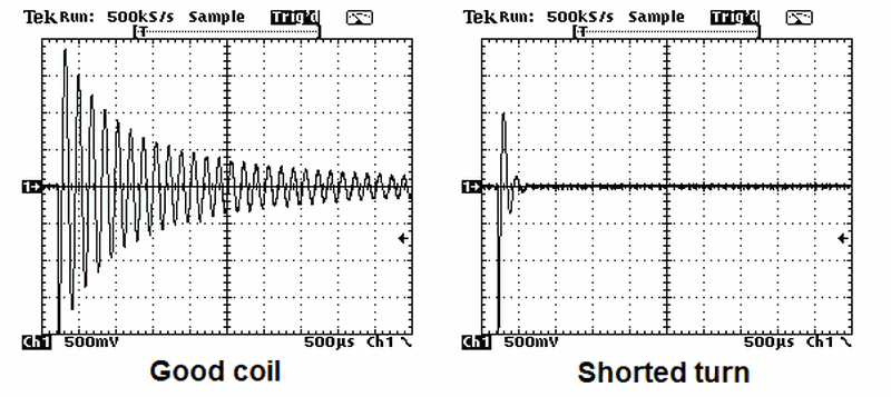
This test device produces square waves by feeding the waveform to a high-impedance JFET buffer and then to half of a hysteresis LM393 pair comparator until the “ringing” voltage drops to approximately 30 mV peak-to-peak.
A CD4518B pair of decimal counters resets at the beginning of each measurement cycle and counts the square waves. The counter outputs in BCD format go to a pair of CD4511B latch/decoder/7-segment driver integrated circuits. At the end of each measurement cycle, the displays are updated with the new counter numbers.
In the unusual event that the counters reach 99, a diode AND gate prevents the counters from “overflowing” to “00” to avoid confusion. The other half of the LM393 acts as an oscillator to set the timing of the measurement cycles.
Theory and Use of the Test Device

Many electronic devices use inductive components in the form of various transformers and coils, etc.
In circuits such as switched-mode power supplies and LCD backlight inverters, and in older CRT flyback transformers and deflection yokes, high voltages are involved, and there is always a risk of insulation degradation between the wires in the windings of these components.
These parts are often difficult to find and are always expensive. When signs of a malfunction point to an internal failure in a transformer or inductor, the technician needs to be sure the part is faulty before calling for a replacement.
Testing Inductive Components
Inductive components are generally divided into two categories. There are high-frequency types, usually with ferrite cores and very low losses. These include switched-mode power supplies and monitor/TV LCD backlight inverter transformers.
This test device is also designed to test low-frequency iron-core transformers, such as valve (tube) amplifier output stages and mains power supplies. Normally, the test device is connected to the primary winding of the transformer being tested.
The test device only provides a low voltage output. In most cases, it can be used to test inductive components in the circuit, provided there are no faults in the circuit or resistive loads in the output windings. If in doubt, remove the inductive component from the circuit and test it. Typical readings
I am grateful to Jestine Yong for providing much of this usage information.
To “get a feel for” what the typical readings are, please try the test device on as many transformers and inductors as possible. There are so many different inductors and transformers that it is impossible to provide “accurate and quick” readings for all of them.
Coil, Transformer Test Device Circuit Diagram
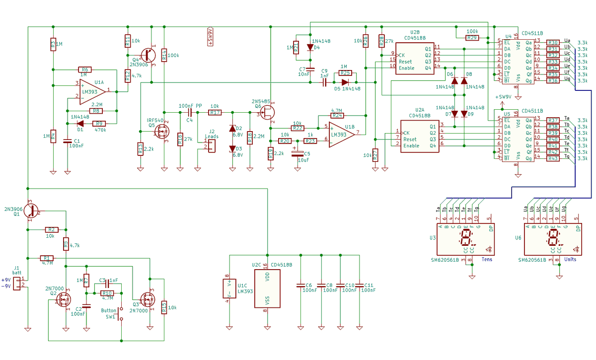
source: zilogbob.com/Basic%20Digital%20Ringer/index.html


