The SMPS Transformer tester is an inexpensive and effective way to test any high Q inductive component. The flyback is particularly useful for performing a quick check on line output transformers and other high frequency wound components such as bias yoke windings and SMPS transformers. Various measurements have shown that SMPS transformers can detect at least 80% of LOPT/FBT errors.
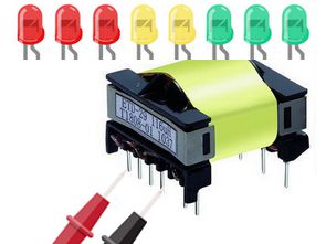
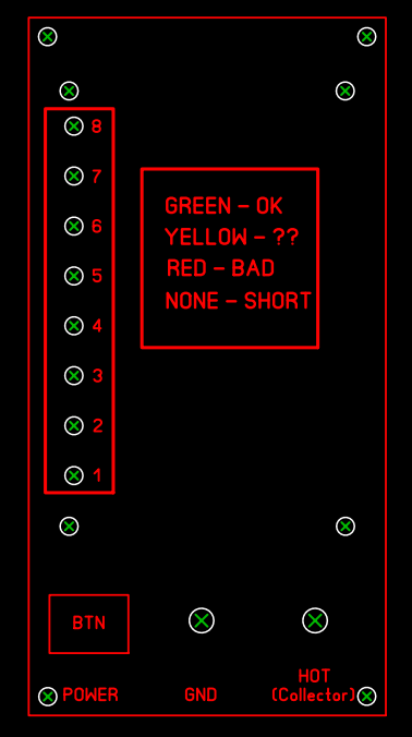
Transformer status information is shown with LEDs. Components in many circuits, including display drivers, SMPS, and tuning circuits, contain low-loss (high-Q) resonant circuits. The testing technique used in this design is based on the fact that many defects in magnetic components result in increased loss = decreased Q.
How does the SMPS Transformator tester work?
The Ring Tester derives its name from the fact that when a rapid pulse of voltage is applied to a high-Q circuit, the tuned structure of the circuit will produce a decreasing AC voltage over several cycles. More loops or “rings” means higher Q. Few or no loops indicate a problem with that component, short circuit, or other problem. This tester provides a quick and easy way to detect such problems.
Consider the waveforms of a flyback transformer, also known as LOPT.
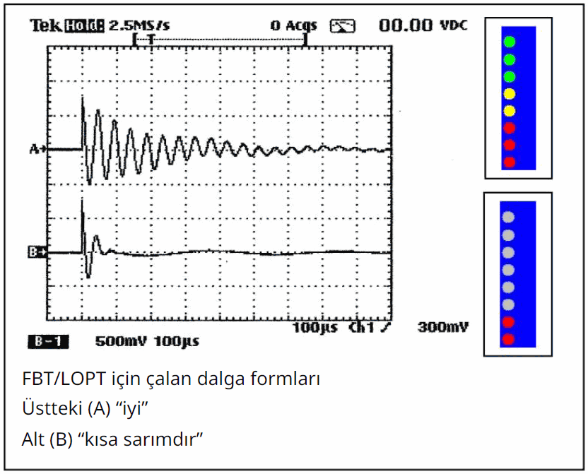
Waveform A shows the ring response to this tester pulse for a good FBT/LOPT. Note the few rings in a faded style. This tester will count rings that exceed its threshold and display them as lit LEDs as shown in the simulation to the right of waveform A.
Different FBTs will exhibit a different response. Some light up all the LEDs as shown above, others light only five or six LEDs perfectly fine. It would be wise to check a well-known ingredient for comparison purposes before deciding good/bad.
High voltage faults that occur only when the power is turned on may not be detected by this low voltage ring tester. Since this unit uses pulses of 600 millivolts or less, it will not detect these faults. However, low voltage, many
Allows in-circuit testing.
Although intended for FBT/LOPT devices, the tester is not limited to them. It will give a rough but useful indication of good/not good for many types of Hi-Q (low loss) inductive components.
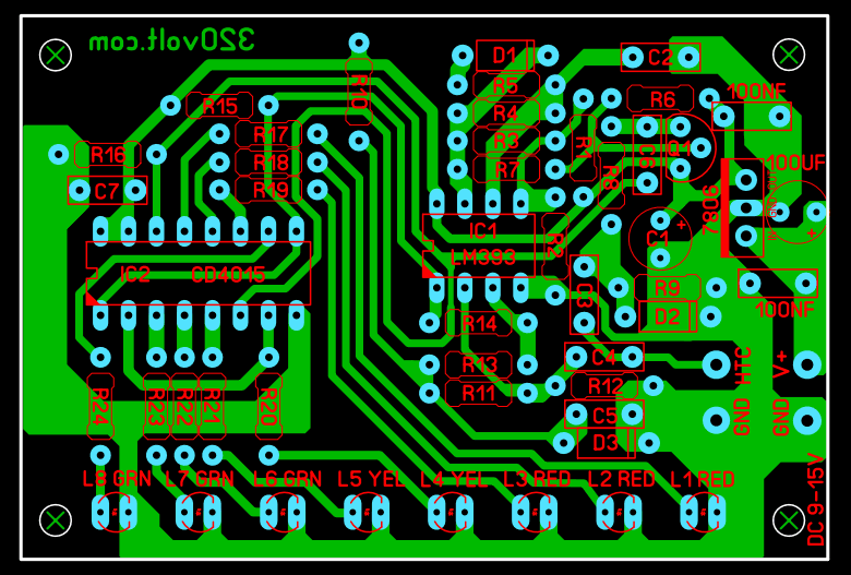
I added a 7806 regulator to the PCB drawing. You can operate it with DC voltage between 9V…15V or you can connect and use 4 1.5v batteries in series as in the application. If you are going to use a battery, mount the 7806 regulator integrated and connect the positive side of the battery to the integrated output.
Sources;
flippers.com/pdfs/BLUE_rt_assembly_manual.pdf – flippers.com/pdfs/k7205.pdf


