Dual, independent power supply, designed to polarize condenser microphones with voltage of +48 V. The built-in transformer and compact size of the board allow you to install the power supply in any electroacoustic device. Recommendations: the device will be particularly useful for constructors and service technicians of audio equipment and for testing microphones.
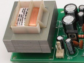
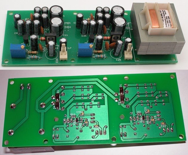
It consists of two twin blocks, and the only odd component is the power transformer. It is a popular and easily available TS2 / 38 with a power of 2 W and a voltage of 24 V at 0.06 A. All components used can easily be bathed in the retail trade. The principle of the device operation will be discussed on the basis of the upper half of the diagram from schematic.
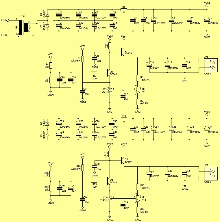
In the power section, the voltage from the transformer is rectified by two semi-bipolar rectifiers (in alternation) connected in series, which after smoothing and filtering through capacitors C1 … C4 and C11 … C14 allows doubling the output voltage (of course with a small load current).
Without load, the voltage on these capacitors is over 70 volts, so be careful. A small resistor R1 and a further packet of capacitors C5 … C10 create another low-pass filter that reduces ripple. The output of this filter supplies the main part of the system – a stabilizer, built of discrete elements.
The working element is transistor Q1 (BD139) – medium power NPN, working in a common collector (repeater) system. The stabilizer is equipped with a negative feedback loop with TL431. The output voltage, after splitting in R6, R8 / R9, is compared to the internal reference voltage of approx. 2.5 V and the difference (error) is amplified about one thousand times.
At the output (“anode”) of the TL431, the NPN transistor is operating, its current increases as the voltage increases at the control input. When this current increases, the voltage drop on R2 also increases, which in turn causes a decrease in the potential of the Q1 base, which translates into a reduction in the output voltage. When the output voltage for some reason starts to decrease, in analogy the voltage on the base and the Q1 emitter will increase.
Since the voltage on the Q1 base is almost 50 V, it is not possible to connect directly the TL431 anode, because the permissible voltage A-K is 36 V. Therefore, I used transistor Q2 in a common base system, which maintains a voltage of about 18V on the emitter.
The output transistor built into TL431 and Q2 works in a cascode configuration, which can sometimes arouse, so just in case, I used a small resistor R5, which reduces this probability.
The 100 nF capacitors located in different places have a similar task. The low-pass filters created in this way will pass the ripple frequency and harmonics without any problems, which will allow the feedback loops to effectively eliminate them.
The TL431 system requires a minimum 1 mA current for correct operation. Since the current drawn from the Q2 emitter is significantly smaller (and depends on the factor ß transistor Q1 and the output load), an additional resistor R3 supports this supply, providing more current. The output voltage is filtered by C16-C18 capacitors. Its calibration is carried out with the R8 potentiometer, which makes it possible to obtain a control range of approx. 44.2 … 50.7 V. The divider current is small and amounts to approx. 350 μA.
According to the Phantom standard, each of the stabilizers can be charged up to 10 mA, although virtually all modern microphones do not require more than 1 … 2 mA. However, be careful not to short the output of the P48 – it may damage the Q1 / Q3 transistor.
![]()
FILE DOWNLOAD LINK LIST (in TXT format): LINKS-26072.zip


ATtiny2313 Programmable Power Time Switch Circuit
ATtiny2313 Programmable Power Time Switch Circuit
Often there is a need to control the working time of the device powered by mains voltage. Different time switches are available in the market, but most of them require time-consuming configuration. In particular, when control is limited to an automatic shutdown after a set time, such solutions become ineffective. For this purpose, the described project was created. Recommendations: the main purpose of the switch is to reduce the consumption of electricity, but it will also be useful to “forgetful” people who do not remember to disconnect devices from the power supply.
Device operation is very simple. If you want to turn on the power supply receiver, press the button located on the edge for a short time. As a result, the time over which the 230 V AC voltage will be applied to the output will be extended by 10 minutes. The maximum time for which the receiver will be powered is determined for 90 minutes.
Schematic diagram of the power switch