Often there is a need to control the working time of the device powered by mains voltage. Different time switches are available in the market, but most of them require time-consuming configuration. In particular, when control is limited to an automatic shutdown after a set time, such solutions become ineffective. For this purpose, the described project was created. Recommendations: the main purpose of the switch is to reduce the consumption of electricity, but it will also be useful to “forgetful” people who do not remember to disconnect devices from the power supply.
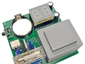
Device operation is very simple. If you want to turn on the power supply receiver, press the button located on the edge for a short time. As a result, the time over which the 230 V AC voltage will be applied to the output will be extended by 10 minutes. The maximum time for which the receiver will be powered is determined for 90 minutes.
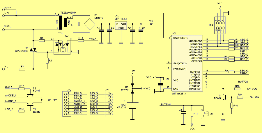
Schematic diagram of the power switch
The current time remaining until the power is turned off is displayed on two 7-segment displays. If you need to turn off the receiver’s power immediately, you can do it by holding down the button for a longer time, until you see two horizontal lines on the display. This function also works when turning on the power – longer holding down the button will immediately turn off the power.
The main task of the device is to reduce energy consumption. Therefore, the aim was for the control device to take the lowest possible current. This task was accomplished by introducing two power sources, the first being a network transformer. The power supply via this source is realized when the device is connected to the network and the power supply to the energy receiver is turned on. When the device is turned off, the transformer’s power supply is automatically disconnected.
The second source of power is the CR2032 battery. This source is used to switch the device from the off state to the state on which the energy receiver is switched on. In order to extend the operating time with battery supply, a number of functions limiting the total energy consumption have been introduced. The most important of them is the automatic transition of the microcontroller to the Power-Down mode in the CR2032 battery mode and the limitation of the high level setting time on the triac control line. Additionally, in order to ensure low energy consumption, when the device is not powered from the power transformer, the device has 7 segments disabled.
The ATtiny2313 microcontroller is the heart of the device. As it was mentioned, the device is powered from two sources – the first one is a power transformer and a stabilizer built of Graetz bridge and integrated circuit LM1117-5.0 with capacitors (C3 … C6) connected in parallel. The second source of power is the CR2032 battery. The switching of sources is realized by means of a double BAV70 diode.
The operation of the microcontroller program depends on which source it is powered from. In connection with the above, a proper signal should be provided to the microcontroller. A block consisting of resistors R14, R15 and R16 and transistor T4 is responsible for this. The function of the function block is to supply the VCC supply voltage if the device is powered by batteries. In the case of power supply from the network transformer, as a result of switching the transistor, there is a mass potential on the line.
Another block to watch out for is the power on and off block. In the presented project, the triak BTA16600B was used to control the power supply. As can be seen in the schematic diagram, the triac controls the power not only on the connectors to the energy receiver, but also on the leads of the network transformer. The triac is controlled using the MOC3062 optotriac. A system with zero detection was applied, thanks to which disturbances introduced to the power grid were minimized. The power supply of the microcontroller from two different sources forced that the optotriac be switched on via a high level.
The last block consists of JP1 and JP2 connectors, to which a 7-segment dual display is connected, T1, T2 transistors and R12 and R13 resistors and R1 … R7 resistors that limit the current of individual display segments. Transistors are used to select the currently controlled display character.
![]()
FILE DOWNLOAD LINK LIST (in TXT format): LINKS-26101.zip


Dual phantom power supply 48 V
Dual phantom power supply 48 V
Dual, independent power supply, designed to polarize condenser microphones with voltage of +48 V. The built-in transformer and compact size of the board allow you to install the power supply in any electroacoustic device. Recommendations: the device will be particularly useful for constructors and service technicians of audio equipment and for testing microphones.
It consists of two twin blocks, and the only odd component is the power transformer. It is a popular and easily available TS2 / 38 with a power of 2 W and a voltage of 24 V at 0.06 A. All components used can easily be bathed in the retail trade. The principle of the device operation will be discussed on the basis of the upper half of the diagram from schematic.
ATtiny2313 Circuit de commutation de temps d’alimentation programmable
Il est souvent nécessaire de contrôler le temps de travail de l’appareil alimenté par la tension secteur. Différents interrupteurs horaires sont disponibles sur le marché, mais la plupart d’entre eux nécessitent une configuration longue. En particulier, lorsque le contrôle est limité à un arrêt automatique après un temps défini, de telles solutions deviennent inefficaces. À cet effet, le projet décrit a été créé. Recommandations: l’objectif principal de l’interrupteur est de réduire la consommation d’électricité, mais il sera également utile aux personnes «oublieuses» qui ne se souviennent pas de déconnecter les appareils de l’alimentation.
Le fonctionnement de l’appareil est très simple. Si vous souhaitez allumer le récepteur d’alimentation, appuyez brièvement sur le bouton situé sur le bord. En conséquence, la durée pendant laquelle la tension 230 V CA sera appliquée à la sortie sera prolongée de 10 minutes. La durée maximale pendant laquelle le récepteur sera alimenté est déterminée pour 90 minutes.
Schéma de principe de l’interrupteur d’alimentation