A simple but functional timer device that allows you to control any device powered by 230 VAC mains in a cyclical, intermittent manner. A typical astable circuit with the NE555 timer integrated circuit. The generator produces pulses with a time constant determined by the combination of a capacitor and resistors. A relay is used as the control element.
220V Timer Device Basic parameters:
Opening time interval: 0.5…15 sec
Closing time interval: 0.5…60 sec
Transformerless Power Supply: 220V AC
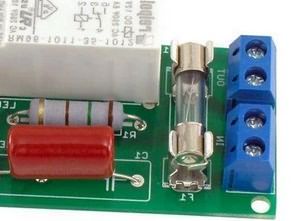
The circuit is used to provide cyclical opening and closing of the device connected to the output. For example, to limit energy consumption and save (by reducing efficiency). The system is powered directly from the 220V AC mains via a transformerless power supply. The 470nF (C1) capacitor limits the current that the device can draw from the network, while the 150-OHM (R1) resistor protects the bridge diode from damage caused by overloading when connected to the network.
The 1M-OHM (R2) resistor is used to discharge the C1 capacitor when the power is cut. The bridge rectifier is connected to the 12V Zener diode, while the 220uF (C2) and 100nF (C3) capacitors act as filters. LED1 indicates the presence of the supply voltage.
Timer System Circuit Diagram
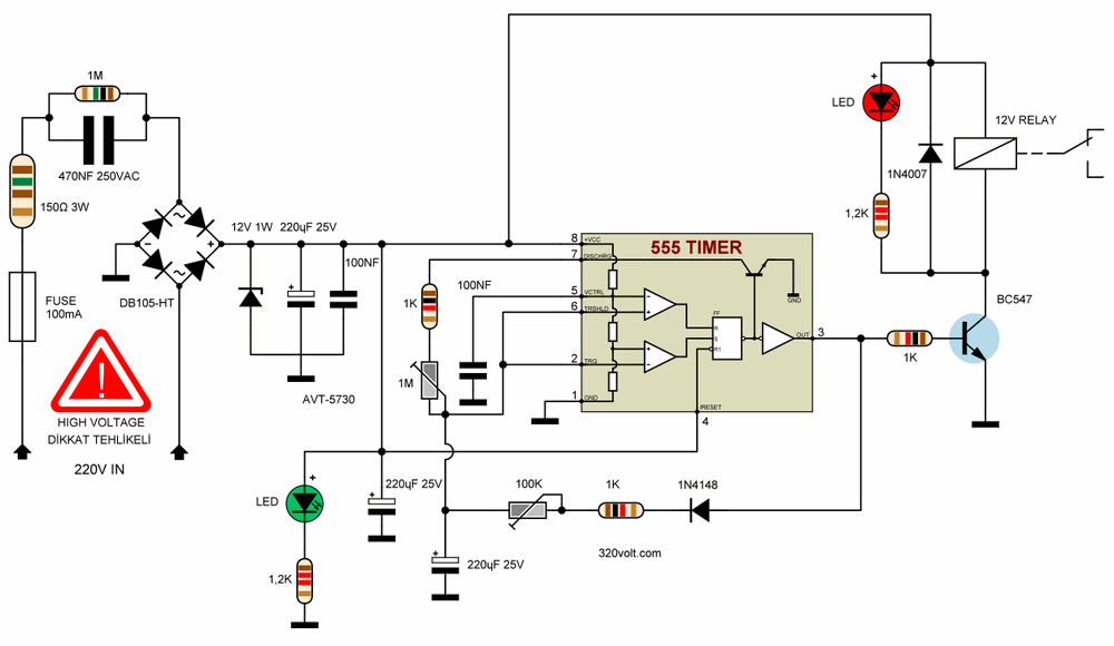
The main element of the circuit is the NE555 timer integrated circuit and works as an astable generator circuit that generates pulses depending on the most commonly used solutions, namely the capacitance of the capacitor C6, the value of the resistance R7 and the setting of the potentiometer PR2.
The other circuit, consisting of the capacitor C5, the resistance R5 and the potentiometer PR1, determines the pause time between successive output pulses. The LED2 diode serves as an indicator that the relay PK1 is active. Two potentiometers PR1 and PR2 allow you to independently set the on time (in the range of approximately 0.5…15 seconds) and the off time (in the range of approximately 0.5…60 seconds).
220V Timer PCB Printed Circuit Diagram
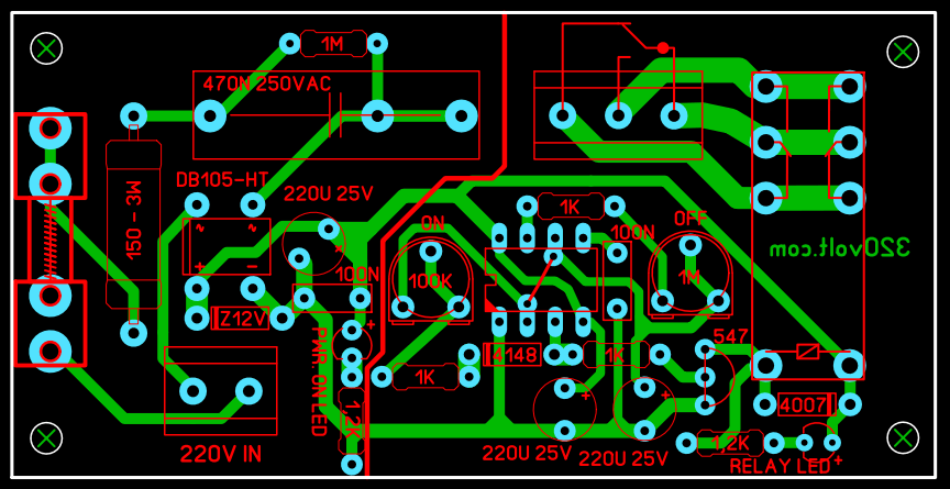
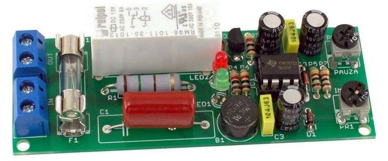
PCB design was made with Sprint layout 6 program. Checked, not tested. You can use 12V 16A Double contact relay. I made a 3-way terminal connection for all relay contacts for different working scenarios.
ATTENTION The circuit works with high voltage, be careful, pay attention to the capacitor connections, if you connect the + – poles in reverse, there may be big explosions at high voltage, use a Fused Electric Line, protective glasses before operating the circuit.
source: ep.com.pl/projekty/miniprojekty/13506-uniwersalny-uklad-czasowy-230-v