
Among simple, low-component-count electronic projects that can be built quickly, NE555-based sound generators always have a special place. This circuit is one of them. Looking at the schematic, an extremely simple ultrasonic sound generator made with a single NE555, a few passive components, and a piezo transducer can be seen.
Although the project is presented as a mosquito repellent, it is more accurate to consider it as an experimental ultrasonic repellent circuit.
For those who want to see how a similar usage logic is handled in commercial products, the mosquito repellent repair review may also be interesting.
What does the circuit do?
Contents
The main task of this design is to generate a high-frequency sound at an adjustable frequency on the piezo element.
The source document states that the frequency adjustment can be made with a potentiometer and that the upper limit can reach approximately 30 kHz.
Since the human ear, especially as age increases, often cannot clearly hear sounds of 18 kHz and above, such circuits may seem to be “operating silently” in practice.
The same logic can also be tested on other animals with different frequency trials.
Therefore, those who want to look at other applications close to this subject can also examine rodent and bird repellent device examples.
Operating Principle of the Circuit
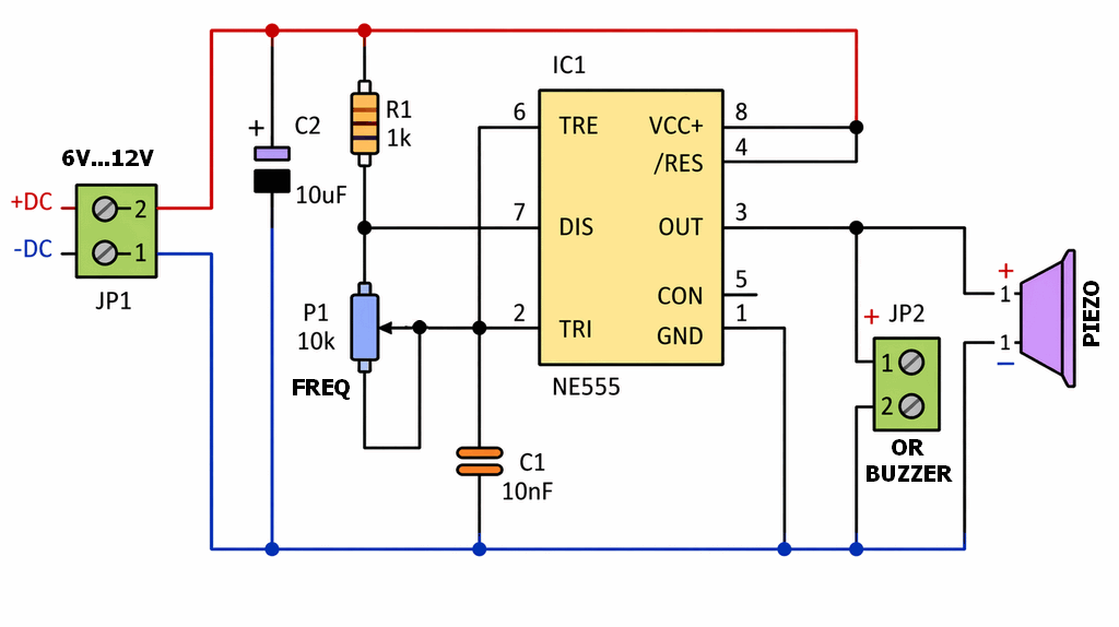
At the heart of the circuit is IC1 NE555. The IC is operated here like an astable oscillator. In other words, it continuously produces a square wave by itself without waiting for an external trigger.
This signal is taken directly from the output pin and applied to the piezo transducer. Thus, the piezo element vibrates and produces high-frequency acoustic energy.
R1 1K, P1 10K, and C1 10nF together form the main network that determines the oscillation frequency.
As the potentiometer is turned, the charge-discharge time changes, and accordingly, the frequency applied to the piezo also changes.
The most educational side of the circuit appears here: with a single NE555, it is possible to see both the adjustable oscillator logic and observe the result directly on the piezo.
For those who want to look at different sound generation applications with the same IC, the adjustable siren circuit with the 555 timer IC is a good comparison point.
Component list and functions
The number of components used in the circuit is quite low. In the source list, there are R1 1K resistor, P1 10K potentiometer, C1 10nF capacitor, C2 10uF capacitor, NE555, and piezo transducer.
This simplicity makes the project attractive both for beginners and for those who want quick results.
| Component | Value | Function |
|---|---|---|
| IC1 | NE555 | Generates the oscillator signal |
| R1 | 1K | Fixed resistor of the timing network |
| P1 | 10K | Frequency adjustment |
| C1 | 10nF | Oscillator timing capacitor |
| C2 | 10uF | Power supply filtering and stability |
| BUZZER | Piezo transducer | Converts the electrical signal into acoustic vibration |
Power supply and connection details
According to the source, the circuit operates with 6-12V DC. The JP1 terminal block is reserved directly for this power supply.
Here, attention must be paid to polarity; the positive and negative terminals are clearly shown in the schematic. The C2 capacitor is also located on the power supply line and helps the circuit operate more stably.
On the output side, a piezoelectric transducer must be used, not a speaker.
The part marked as BUZZER in the schematic should actually be considered as a piezo transducer, not an active electronic buzzer.
Because the element that produces the sound is directly the frequency of the NE555. If an active buzzer with its own internal oscillator is used, the intended operating logic of the circuit will be disrupted.
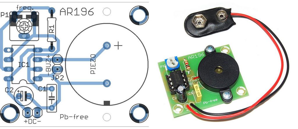
Easy Circuit Assembly
Since the board size is approximately 41×33 mm, the circuit is quite compact. In the assembly note in the document, it is recommended to start soldering with the lowest-profile components and then move on to larger parts.
This is a classic but correct order. If the resistor, then the small capacitor, IC socket, potentiometer, terminal block, and finally the piezo connection are assembled, the process proceeds more cleanly.
Using a socket for the NE555 is not mandatory, but it is a good habit. This way, soldering is completed without overheating the IC, and it can be easily replaced later if necessary. Also, if the cable length is not extended too much in the piezo connection, the circuit will remain more organized.
Adjusting the Circuit
The only adjustment component in the circuit is the P1 potentiometer. As this potentiometer is turned, the frequency changes.
At lower settings, the sound may become closer to the audible range, while at higher settings the device may seem silent, but the piezo may still be operating.
Therefore, the most accurate method is to try different adjustment points and observe the practical result in the operating environment.
This type of circuit can be used for testing purposes in open areas, near windows, at warehouse entrances, or at points where animal entry is not desired.
For those who want to see different outdoor deterrent examples, the electronic pigeon repellent project may also give an idea in terms of similar application logic.
General Features of the Circuit
- It can be built with very few components.
- Since it is based on NE555, it is easy to understand.
- Frequency adjustment is made with a potentiometer.
- Since a piezo is used, current consumption is low.
- Thanks to its small board size, it is easy to enclose.
Things to pay attention to in practice
There are a few important points that should not be overlooked when building this circuit. First of all, it should not exceed 12V, because the source range is given as 6-12V DC.
Secondly, the piezo element must be connected with the correct polarity. The document specifically states that the red wire is positive and the black wire is negative.
Thirdly, the effect of ultrasonic repellents may vary depending on environmental conditions, the target creature, distance, and mechanical placement.
Note: This project is a technically working simple ultrasonic sound generator; however, its mosquito repellent effect should not be considered a guaranteed solution that gives definite results. The most correct way to use it is to build it as an experimental hobby circuit and observe it under different conditions.
Source: arlisklep.pl/files/ARLI/AR196.pdf


