Embedded ethernet enables microcontroller-based projects to send and receive packets over the network. It contains all the circuits needed to enable 10BaseT communication. The board is designed to minimize the number of pins required to interface with microcontrollers.
Three control signals (15 signals) along with an 8-bit bus, a 4-bit address bus, and an optional interrupt signal are all that is needed to control the board. This was made possible using the Crystal CS8900 ethernet transceiver operating in 8-bit mode.
All necessary information, schematics and source codes to realize TCP/IP communication over Ethernet are detailed on this page. I’m using a Microchip PIC16C74 controller in this project, however, any controller with sufficient port capacity will work. This includes the popular Motarola 68HC11.
The project described here consists of two parts. Test circuit using real embedded ethernet card and PIC16C74. The code running on the PIC includes the drivers for the card and the TCP/IP layers necessary to communicate on the network.
Crystal CS8900 Overview
The Crystal CS8900 is a single-chip solution that can interface directly to the analog side of 10BaseT ethernet using only an isolation transformer and some passive components. The CS8900 has 4K integrated memory that allows the microcontroller to receive and send packets asynchronously. This eliminates any timing issues that might normally be present and allows even the slowest microcontroller to talk over ethernet. The CS8900 itself runs at 20Mhz and requires an external crystal. Most ethernet transceivers run directly on the ISA bus and use DMA to access external RAM for incoming and outgoing packets and control information.
The crystal part also works in this mode, but it also has an 8-bit mode. Using this mode is similar to checking ports in PC architecture. For a write operation, the address, for example 0x300, is placed on the address bus, the data is placed on the bus, and then the /IOW signal is switched. The address decoding logic “sees” that the port address (0x300) on one of the boards is there, and then retrieves the data from the bus.
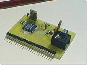
Schematic of the embedded ethernet card shown above
This board was designed using ExpressPCB. The software for board layout design can be downloaded for free from their website and the ordering of boards is automated though the software package.
It should be mentioned that you will need to use a professionaly designed board for this project since the CS8900 is only available in a 100 pin QFP surface mount package. Don’t panic! I didn’t know anything about surface mount technology until I started this project, either. Here’s the technique I use to solder the chip to the board:
• Use a 3x/4x magnifying lamp.
• Get a soldering iron that has adjustable temperature settings, use 450-500 degrees farenheit.
• Since the CS8900 uses .020 inch spaced leads, use a tip that has a diameter less than this, I use a .015 inch tip.
• Get some flux at Radio Shack and place a very small amount on the surface mount pads.
• Get some silicon-based adhesive from Radio Shack and place a small amount on the belly of the CS8900. This will allow you to place the part and center it over the pads. Take your time and go slow.
• When the silicon hardens, heat up the iron and on the outer-edge pins, place your iron on the pad and allow a small amount of solder to flow. What we’re trying to do here is anchor the part on the four sides. Repeat for each side.
• From this point on, don’t use ANY SOLDER. The board as manufactured by ExpressPCB has been tin-lead plated and the pads already contain all the solder necessary to form a good inter-metalic bond. Merely touch the iron to each pin and allow the solder to reflow. This goes very fast and you can solder all the remaining 96 pins in under 5 minutes.
Overview of the test circuit A Microchip PIC16C74 is used to drive the CS8900 and to implement some basic TCP/IP functionallity. The test circuit, once connected to the ethernet backbone, can be pinged from another node. Also, a Windows Sockets program is included that connects to the test circuit who is listening on UDP port 7 (echo). The echo service sends back any data that it receives.
The programs are all setup to use IP address 192.168.1.2 and Ethernet address (also called an OUI- Organizationally Unique Identifier) of 00:00:00:12:34:56. Since these are ficticious numbers, you may need to change them. Two places that need modification, the program running on the PIC has equates for these values and the IP address is hard coded in the testudp.c program. If you don’t change them, and are testing under NT (recommended) you may need to add a static route using the command route add 192.168.1.2 your.ip.gateway.address. This will cause all traffic to the board to go through the default gateway of you’re local machine.
Schematic of the test circuit


In conclusion: I originally worked on this project in anticipation of selling the technology but circumstances changed and I hope that the embedded community will benifit from this work. Embedded ethernet is not without it’s problems. For example. I was planning on using an EEPROM as the storage for packet data but quickly realized that the write/erase times would not be sufficient. Typical write times are 5ms which brought the ping time for a 500 byte packet to 1.5 seconds. I believe now that the key to using this technology is to write specifically to the problem domain.
By Gary T. Desrosiers
Copyright © Gary T. Desrosiers, 1998
Embedded 10BaseT Ethernet PCB files (express pcb)


Simple OTL Amplifier Circiut
Amplifier Circiut Npn and pnp transistors built on 4.5 volts, an amplifier circuit is working with 3 alkaline batteries can be used with LED warning when the battery level drops gives 99s also prepared with protel pcb file available
Simple OTL Amplifier Schematic