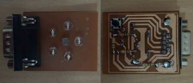
In the new version issued to 10 The number of colors, color identification and color separation feature was developed and added to a method for the sensitivity has been increased. Also feature full contact with the surface to be detected with the sensitivity calibration and the requirement has been removed. Color Sensor detection circuit, located on 5 different colors of LEDs in 16 different combinations and can be activated with different colour shades with light illuminating the surface to be detected of the reflected light in the form of making separations and evaluate the impact on the LDR works.
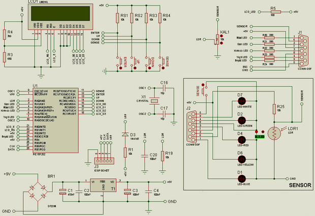
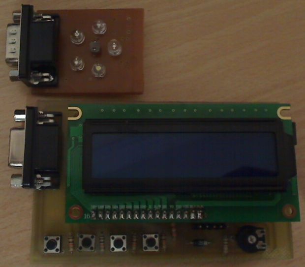
Sensor sheath in transparent bright LEDs in the circuit were used. Also to improve the efficiency of the detection process, the sensor and external ambient light into the Black Box circuit is taken from the minimum in a way has been affected. The sensor control circuit are connected to each other via cable with 9-pin serial port circuit. The LEDs on the sensor circuit are arranged in the shape of the work. 2^5=32 different ways to use it were provided for, however, in the alternative, the effect on separations a total of measured values is small, and the low probability of detection associated with the duration of the impact was sieved to work. LDR in the environment since it takes time to adjust to the light that which was used to study influence the outcome.
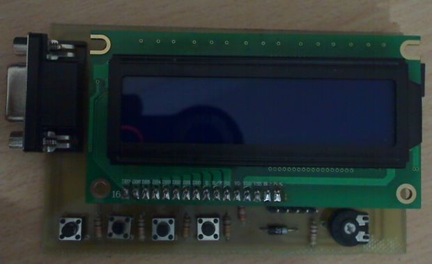
What needs to be done in order to reach the correct conclusions from the color sensor following step-by-step explaining;
• The menu by entering CALIBRATION screen opens
• CALIBRATION while the contact surface by contacting the sensor circuit is on the screen, the pot on the control card by using a value of 160 are synchronized
• COLOUR TREASURE screen up/down the color that will be introduced with the buttons is selected. – process is started by pressing the button for the promotion. When the promotion is finished, the measurement value is displayed on the screen of that color. The precision value for the determination of this value should be recorded in a table.
• All the colors that will be used in this way the color values to EEPROM after it is introduced is automatically saved.
• By using the sensitivity value obtained from the color value table that is generated for the calculation of the table are sorted in descending order. Difference by subtracting a value close to the value under each line of the table. Half of the smallest of these values is the sensitivity. This value is SENSITIVITY by opening the screen must be entered. As an example, in the project file Renkler.xlsx file can be examined.
• The exit option exits the menu with.
the
Color value calculation
The color value of the LED light and the reflection of the reflection detection from the surface is found with the calculation of the effect on the LDR. At each color change is measured and the effect on the LDR for this process are stored in an array. With the addition of LEDs flashing, steady remain in the dark for a period of LDR by ensuring that during the previous measurement of the effect of the measurement at that time is reduced. The LDR value of the LEDs to be active LDR measured after a certain period of time to adapt to the current situation is intended.
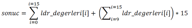
LED that indicates the status of the situation impact the contribution to the result of the last seven in the table is bigger than the others because these values have been collected among themselves after being multiplied by 15 and added to the result. Thus, it was attempted to increase the difference between color values software. Can be rewritten as the formula used to determine the color value ultimately.
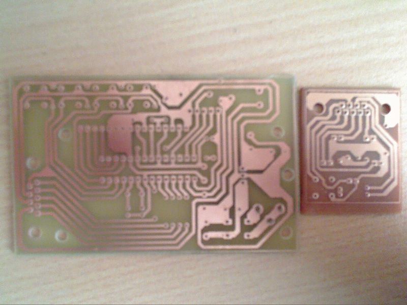
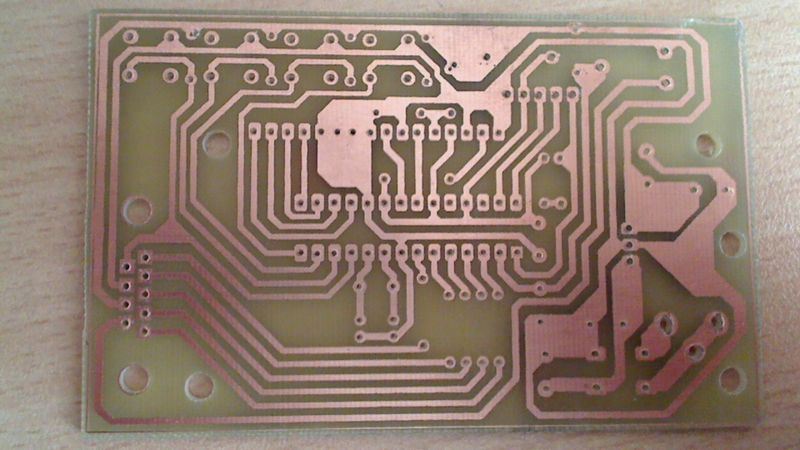
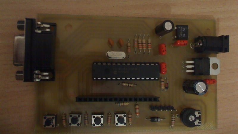
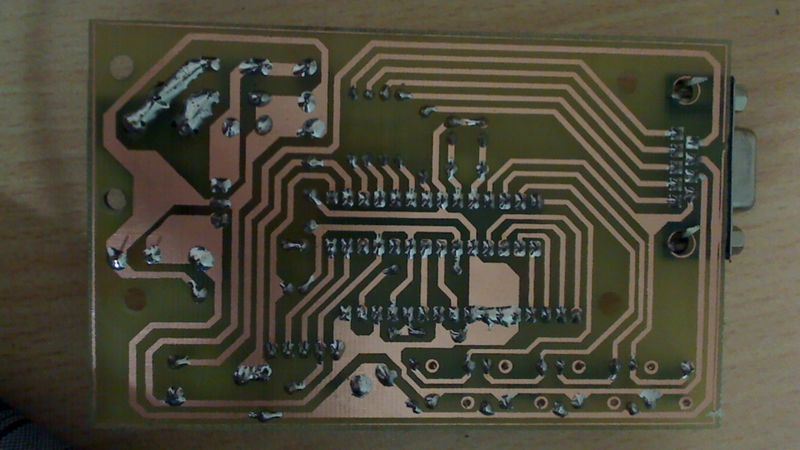
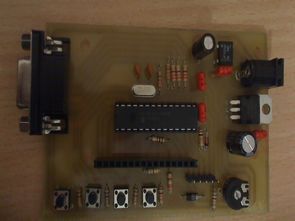
PIC18F252 Proteus isis ares pcb simulation files and source code belonging to a color detection circuit:
FILE DOWNLOAD LINK LIST (in TXT format): LINKS-25452.zip


Electronic Calculation Program For Radio Amateurs
500kb size calculation is very useful and handy program that can do a lot by electronic
Antenna ERP calculations.
Debilitating calculations.
Audio filter design.
Coiled accounts.
Decibel calculations.
Great-Circle map and the calculator.
HF Filter Calculation.
Antenna HF Calculation.
Op-Amp Calculation.
Determine QRA (rear) / Longitude Latitude.
Radio Horizon account.
Satellite Orbit Calculation.
Timers.
The Calculation Of The Zener Diode.
Resonance and bandwidth.
Metric and other conversions.
Farbe-Erkennung-Schaltung PIC18F252
In der neuen version ausgestellt bis 10 Die Anzahl der Farben, Farbe, Kennung und Farbe Trennung-feature wurde entwickelt und Hinzugefügt, um eine Methode für die Empfindlichkeit erhöht wurde. Funktion auch vollen Kontakt mit der Oberfläche erkannt werden, die Empfindlichkeit der Kalibrierung und der Anforderung entfernt wurde. Color-Sensor-Erkennung-Schaltung, die sich auf 5 verschiedene Farben von LEDs, die in 16 verschiedenen Kombinationen und kann aktiviert werden, mit verschiedenen Farben, die mit Licht die Beleuchtung der Oberfläche werden erkannt, der das reflektierte Licht in form von Separationen und Bewertung der Auswirkungen auf die LDR funktioniert.