The PIC18f4550 microprocessor based pong game PIC18f4550 The first player to reach 20 points in the Pong Game wins the fireworks animation with leds.
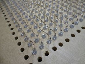
The PIC18f4550 works at 8MHz, the display is made up of 900 LEDs arranged in 30×30 size matrise, and besides table preparation, the most demanding part will be 900 strings and soldering.
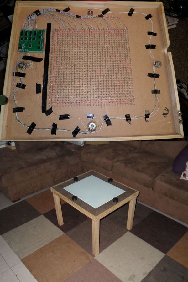
Game circuit ULN2803 and 74373 integrations are used in the LED driver section. The player selection is controlled by the start buttons.
It is said that the PIC18f4550 game circuit power supply uses 4 pieces of 2500mAh rechargeable battery and it is based on 2 hours of playing every day for half an hour
PIC18f4550 game project software has source code and hex, pcb, gerber files prepared with swordfish basic,
Test video PIC18f4550 game project
source: instructables.com/id/Super-Pong-Coffee-Table/
FILE DOWNLOAD LINK LIST (in TXT format): LINKS-25928.zip


4 Spieler Pong Spiel PIC18f4550
Das PIC18f4550 Mikroprozessor-basierte Pong-Spiel PIC18f4550 Der erste Spieler, der im Pong-Spiel 20 Punkte erreicht, gewinnt die Feuerwerk-Animation mit LEDs.
Der PIC18f4550 arbeitet mit 8 MHz, das Display besteht aus 900 LEDs, die in 30 × 30 Matrizen angeordnet sind, und neben der Tischvorbereitung werden 900 Strings und Löten am anspruchsvollsten sein.
Spielschaltung ULN2803 und 74373 Integrationen werden in der LED-Treibersektion verwendet. Die Spielerauswahl wird durch die Starttasten gesteuert.
Es wird gesagt, dass das PIC18f4550 Spiel Schaltung Netzteil 4 Stücke von 2500mAh Akku verwendet und es basiert auf 2 Stunden spielen jeden Tag für eine halbe Stunde
PIC18f4550 Spiel-Projekt-Software hat Quellcode und Hex, PCB, Gerber-Dateien
Car Amplifier Circuit TIP142 TIP147 200W DC DC TL494 EI33
Car Amplifier Circuit TIP142 TIP147 200W DC DC TL494 EI33
Previously shared RMS 250W auto amplifier JBL filter SMPS EI35 SG3525 project is similar to the PCB design is a very regular auto amplifier circuit. You can use 2x100w rms stereo or 200w rms mono, which can be controlled by bridge connection as well as bass control with cross over circuit with adjustable TL072P op amp at the main entrance floor.
TIP147 TIP142 darlington transistors are used on the power amplifier floor, and BDW83C, BDW84C can be used instead.
The symmetrical + 35v -35v TL494 DC DC converter circuit required for auto anfin operation is provided. The supply of the cross over circuit is regulated by + -35V TIP41C TIP42C transistors (+ -15V)
The power core is EI33, AT, ATX power supplies. A lot of articles have been shared about the use of this transformer. In this application, the method of using transformer was made as mentioned in the article of DC DC Converter 200W 2X30V SG3524 SG3525 using EI33 Transformer. The MOSFETs IRF1010N driven at the output of TL494 can be replaced by IRF3205, IRFZ44, 50N06.
The “REM” section on the DC DC power supply circuit with the TL494 PWM control integra- tion. A cable from the ignition wire of the car will be pulled in. This section allows the system to close when the car is not running. You need to give + 12v to your section.
Jeu de pong à 4 joueurs PIC18f4550
Le jeu de pong à base de microprocesseur PIC18f4550 PIC18f4550 Le premier joueur à atteindre 20 points dans le jeu de Pong remporte l’animation de feux d’artifice avec des leds.
Le PIC18f4550 fonctionne à 8 MHz, l’écran est composé de 900 LED disposées en matrise 30 × 30, et en plus de la préparation de la table, la partie la plus exigeante sera 900 cordes et la soudure.
Les intégrations du circuit de jeu ULN2803 et 74373 sont utilisées dans la section du pilote LED. La sélection du joueur est contrôlée par les boutons de démarrage.
On dit que l’alimentation du circuit de jeu PIC18f4550 utilise 4 pièces de batterie rechargeable de 2500mAh et est basée sur 2 heures de jeu chaque jour pendant une demi-heure
Le logiciel de projet de jeu PIC18f4550 a du code source et des fichiers hex, pcb, gerber préparés avec l’espadon de base,