Introduction to Visual Basic : In electronics, there is always a situation where you are doing a calculation or want to automate a process. Implemented simple Visual Basic Projects.

Calculate RC filter

There are always situations where you reach for the calculator in the electronics lab. A typical example is the calculation of an RC low pass filter. Every time you think about it, what was the formula again? Oh yes:
And then comes the volumes issue. The formula applies to frequency in hertz, resistance in ohms, and capacitance in farads. But the table has capacitors in pF, nF or µF. You have to be careful not to miscalculate by a few orders of magnitude. A solution would always be to calculate with kHz, Ohms and nF:
And if you always have a small program at hand on the desktop, nothing can go wrong. So this is a typical task for a small VB program of your own.
Input is via two text windows, Text1 and Text2. The “Calculate” button starts the calculation. The result appears in the Text3 text field. You can use a label for the output as well as any other label in the form.
Double-clicking the button opens the editor. And here you enter the base text you want. In this case, there are no more than five rows. The result is rounded to three decimal places. This allows you to view the entire range from 1 Hz in kHz to many MHz.
LED alternative indicators

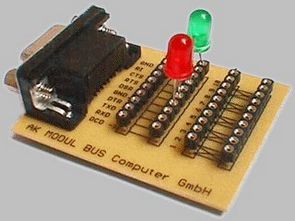
Visual Basic not only calculates electronic assemblies, but also directly inspects them. It is particularly easy via the RS232 interface. The example shown here uses ELEXS.DLL. This file should be copied to the C:\Windows directory. All notifications are now in the ELEXS.BAS module. This file should be included in all new projects. Only capital letters are used in all function names. This is important because starting with VB5 case is no longer ignored.
The BLINK program controls DTR and RTS in phase opposition, that is, whenever DTR is turned on, RTS is turned off. So you can set an alternate flasher by connecting a red LED to DTR and a green LED to RTS.
Alternating flashers can also be implemented with an output line by connecting both LEDs in anti-parallel. One lights in the positive phase and the other in the negative phase.
Short time measurement up to 100 ms

Here, pulse durations from a few microseconds to 100 milliseconds are measured at the CTS input. The ELEXS.DLL function TIMEREAD provides a time resolution of one microsecond, so serious applications in the electronics laboratory are possible.
The measurement runs in a timer procedure with the REALTIME setting. Two upstream loops ensure that the actual measurement starts with a low/high edge. The time is then measured while the CTS is high. If a time limit of 100 ms is exceeded, each of the three cycles is terminated prematurely.
Simulation of lamp circuits with Visual Basic

Let’s say you are at the beginning of your education in the electricity trade. Your foreman has assigned you the task of installing a circuit breaker on a perforated mounting plate using electrical material found in the workshop. The picture shows the finished “model build” that you should follow.
The foreman will then check your work and run the circuit himself, as you are still at the beginning of your training. When connected to mains voltage, the switch should be able to turn the lamp (shown here as a light-emitting diode) on and off.
The master does not like your first application, because what matters is the technically correct application and the beauty of the work you will see after his encouraging explanations. It reminds you again to do the task exactly as the pattern tells you. We have learned a lot through imitation since childhood, so please do the same now by downloading the program example here and launching your Visual Basic development interface.
Also, in a text field to the left of the program flow, you actually
The switching status of the button representing the off switch should be displayed. You have installed the Visual Basic development environment on your computer and installed the small program. Now if you select individual components of your circuit from the tool collection on the left, eg. B. Click on the individual lines (Line), at the bottom right you will get information such as width (BorderWidth), color (BorderColor), start and end coordinates (X1, Y1,X2,Y2), design of the line. (Border Style) . For example, by clicking For example, change the color by selecting another color in the Palette or System area. Or you get a different width for the line representing the line. You can always go back to the given paradigm.
If you move one of the lines, it will only stick in certain places. With a little imagination, this could be likened to building a plumbing circuit on a perforated metal plate; this only allows components (junction boxes, switches, etc.) to be installed at specified intervals due to the regular arrangement of drilled holes. point.
You can turn this capture off from the top menu, if you check the pseudo checkbox in Align Control to Grid under Tools Options General it will disappear and you can tick it again later if you want. As the junction boxes I chose the so-called shape controls where you can change the shape and color. You can also get information about this by clicking on the bottom right.
As the key, I chose the so-called frame symbol, which allows me to combine buttons into groups. Inside there is a button CommandButton which symbolizes the switch during shutdown. The lamp consists of a lamp housing and pseudo-shapes, such as the lamp shown here as a red light emitting diode with two small white shapes in the upper left corner of the symbol. The emitting diode achieves a realistic appearance. Please take a closer look at its features in the area below!
In a text field next to the switch, the switching status is indicated by displaying 1 for the on state and 0 for the off state. When the program is started, the lamp should only light up when the button is pressed. Pressing it again, turning off the lamp, etc. It means.
First, Dim a As Byte defines a variable a used in the program. When you click the button, enter the text shown in the picture between Private Sub Command1_Click() and End Sub. If you click on Form1, two lines will be added there as seen in the picture.
How does the program work after launch? When the button is clicked, variable a is incremented by 1, but only until 1 is reached, because in reality a kill switch has only two switching states, i.e. on and off. If 1 is exceeded, a becomes 0 again. This is done with If Then.. End If statements.
The value of a is displayed in the text box next to it.
This is followed by evaluation with Select Case a. If the state of a is 0, the LED should not light (indicated by Shape4.FillColor = &H80&), so the shape assigned to it is displayed in dark red, if a = 1 (switch in the on position), it lights up with symbolized bright red. The hexadecimal value of the color is now &HFF&. End Select should appear at the end of the Select Case. If the program is started for the first time, the LED should not be lit.
Source : elo-web.de Visual Basic Electronic Projects source code files Alternative link:


LM35 Sensor Heater Control PIC16F877 Thermometer
In this project using PIC16F877 microcontroller integrated temperature-controlled thermometer did. Thermometer for the implementation of PIC 16F877 / D converter property was utilized. Half-output unit, the LCD screen is used. But the main feature of the application in a specific band gap temperature (20C-25C) in the output due to temperature above or below the temperature according to the fan or heater to run.
LM35 Thermometer