Bicycle gear manufacturing isn’t exactly our area of expertise, but it could be useful in various mechanical projects. This software makes it possible to create gears of desired dimensions, circular or oval, compatible with different connection types.
It’s possible to design gears suitable for older and non-standard cranksets, as well as experiment with oval gears.
Program Menu and Settings
Contents
The program only has two main menus:
File / Settings
File / Print
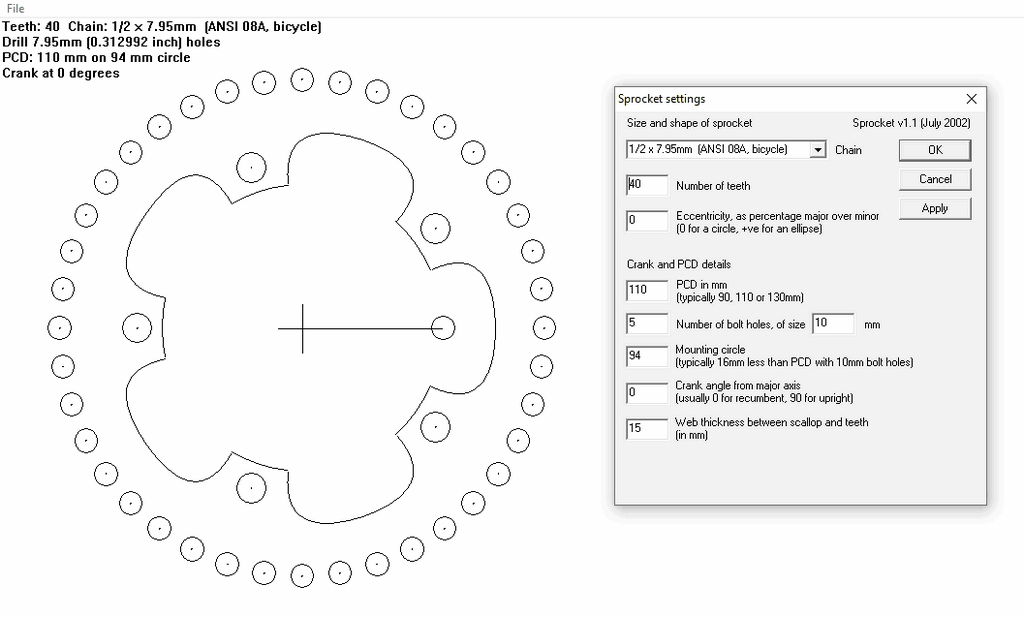
File / Settings
The following parameters can be set in this section:
Chain pitch: Usually 0.5 inches
Number of teeth: The total number of teeth on the sprocket
Eccentricity: Expresses the difference between the major and minor axes as a percentage. For circular sprocket, leave 0.
PCD (Bolt circle diameter): Usually 110 or 130 mm, but any desired value can be entered
Number of bolt holes: Usually 5
Bolt hole diameter: Usually 9 or 10 mm
Mounting circle diameter: In most cases approximately 16 mm smaller than the PCD (for 10 mm bolts)
Angle: The angle between the crankset and the main axis of the sprocket
Material allowance: The thickness of the metal between the teeth and the weighting gaps. This value can be increased to improve durability.
A minor drawback of the program is that although the settings are saved as files, the entered values are already few and easy to remember. All measurements are in the metric system.
Printing and Manufacturing the Gear
This command prints the generated gear template as a single or multiple pages. When using multiple pages, a 15 mm overlap and center lines are included; this allows A4 printouts to be easily combined. Using an A3 printer is much more practical.
The printed template is glued to a 2 or 2.5 mm thick duralumin sheet using spray adhesive. As the thickness increases, the torsional resistance of the gear increases; however, it should be noted that in multi-speed chains, the tooth thickness should not exceed 2 mm. Gluing a blank sheet of paper to the back protects the surface from scratches.
The holes are first centered (marked with a punch).
They are then drilled, first with a small drill bit, then enlarged with an 8 mm drill bit.
The outer contour is cut with a jigsaw or metal saw.
As much material as possible is left on the teeth.
Center and relief holes are drilled as desired.
The next stage is shaping the teeth individually, which is quite time-consuming. Especially if using 2.5 mm thick steel, the teeth should initially be left a little thicker. It’s recommended to use a new chain for testing. The chain should move smoothly over the teeth without snagging, and without lubrication.
The process speeds up with experience. For example, completing a 60-tooth sprocket can take several hours; however, it’s possible to see this process as an enjoyable endeavor.
As a practical method, the teeth can be fine-tuned by attaching the sprocket to the crankset and using a file with the other hand while pedaling. This works almost like a “lathe made with what’s available.”
Making Gear Shifting Easier

For smoother gear changes:
The gears can be filed down alternately on both sides (Hyperglide-like)
Or, all 4th or 5th teeth can be completely removed, except for the smallest gear.
These methods significantly improve chain shifting, especially on larger gears.
Correct Positioning of the Oval Gear
The Q-Ring oval gear user manual emphasizes an important point:
In ligerad and trike systems, the adjustment rules given for classic upright bikes should not be applied directly.
This is because the chainstay, the direction of force application, and the rider’s seating position vary significantly depending on the design. Therefore, the angle of the oval gear relative to the crankset may differ on each vehicle.
To meet this need, Q-Rings has developed a highly flexible gear design with 35 mounting holes around its circumference, specifically for the ligerad and trike world.
Identifying Dead Points
First, the points where the force applied to the pedal is minimal must be identified. In classic bicycles, these are called Top Dead Center (TDC) and Bottom Dead Center (BDC). However, these definitions can be confusing in leaning bikes.
Therefore, two more appropriate terms are recommended:
Near Dead Center (DIRECTION): The position where the pedal is closest to the rider. Far Dead Center (TDC): The position where the pedal is furthest from the rider. The cranksets should be fixed in this position.
Final Adjustments
The oval gear is placed on the crankset with its minor axis perpendicular to the chain. Then, riding for a long time (many kilometers) is necessary to allow the legs to get used to the new pedaling feel.
Then, the gear:
If adjusted slightly later → better acceleration
If adjusted slightly further → higher maximum speed
If more force is desired at the start of pedaling, the gear can be adjusted clockwise; for more force towards the end of pedaling, it can be adjusted counterclockwise (viewed from the right).
Source: velomobile.org/workshop/construction/transmission-gl/93-oval-rings-program