Electronics were beginners can implement a simple control circuit is simple and low cost construction. Prepared circuit thanks to those who contributed.
Circuit diagrams and printed circuit board top view of the bottom;


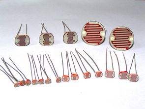
LDR CONTROL CIRCUIT OPERATION
A circuit which is sensitive to LDR LDR dir.ışıg control circuit, as soon as the light falls on the resistance value drops to very small proportions. In this way, the base terminal of the transistor BC548 is provided to + voltage and transistor arrive comes to insulation. If light falling on the range of ARD ARD then the resistance will rise and the collector-emitter of the transistor conduction current flow by providing reacted LEDs are burned. Thus, our circuit is used to provide light in the darkness.


Winamp IR control Circuit VisualBasic PIC16F627 RS232
Winamp can be used to control a variety of programs with some ready-made controls, but these controls are difficult to find compatible IR control circuit and control the problem disappears.
IR transmitter circuit 16f627 microcontroller is based on the 6 button control receiver circuit MAX232 and IRM8061 doing eye catching and consists of a few passive components. The eye catching enough to connect the different models used in the right leg
Prepared by the C language source code of the circuit and control software source code in Visual Basic are prepared. Winamp outside the control circuit can be useful in different projects.
Winamp IR control Circuit