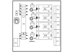
The main parts of the switch inputs is the decimal counter CD4017. Resistors R5 and R6 serves to limit the input current to the counters and, together with capacitor C1 form the RC divider. His task is to prevent multiple switch, when pressing a button, the influence of mechanical oscillations of the contacts of the button. To the counter read, must be on pins ENA and reset log. 0. On the outputs 0 – 3 are connected resistors for limiting the current of the LED diode and transistorem. Transistory here have the function switch and operates relays, for which, at rest de-energized, the contacts is connected the input audio signal. When the switching transistor switches the position relay and connects to the output the appropriate input stereo signal.
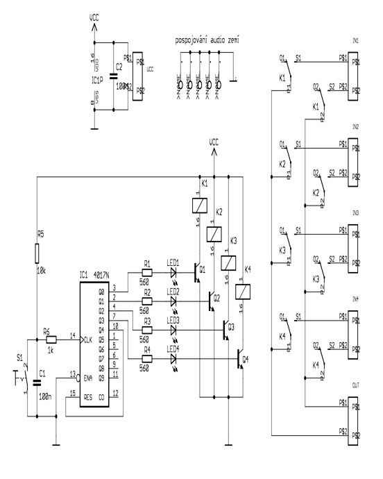
Audio Input Selector Circuit schematic
When switched input is active 1. After pressing of the button activates the following input. At the push of a button when an active input 4 is activated again enter 1. This is achieved by connecting the outlet 4 and reset.
Audio Selector Circuit
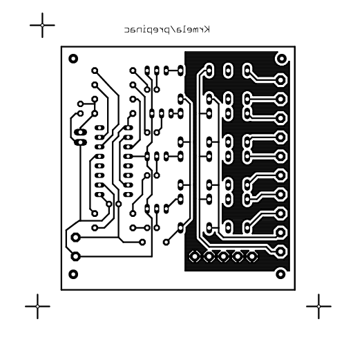

![]() audio source selector circuit pcb schematic all files alternative links:
audio source selector circuit pcb schematic all files alternative links:
FILE DOWNLOAD LINK LIST (in TXT format): LINKS-25538.zip


TDA7490 Class-D Amplifier Project
The output stage of the TDA7490 amplifier in class D The core of the end stage class d circuit is TDA7490 from the company STMicroelectronics. The way in which this amplifier works, was discussed above. Here will be dismantled just a function nejdůleţitějších components. On pin 8 generates a modulation signal, or it is possible for him to bring an external modulation signal. The frequency of the generated signal is according to given the values of capacitor C17 and resistor R13 according to equation.
Audio-Eingang Selektor Schaltung
Die wichtigsten Teile der Schalter-Eingänge ist der dezimal-Zähler CD4017. Die widerstände R5 und R6 dient zur Begrenzung der Eingangsspannung für die Zähler-und, zusammen mit dem Kondensator C1 bilden die RC-Teiler. Seine Aufgabe ist es, zu verhindern, dass mehrere Schalter, die beim drücken einer Taste, wird der Einfluss von mechanischen Schwingungen der Kontakte der Taste. Um den Zähler zu Lesen, muss an den pins ENA und reset-log. 0. Auf die Ausgänge 0 – 3 verbunden sind widerstände zur Begrenzung des Stromes der LED-diode und transistorem. Transistory hier die Funktion, Schalter und relais arbeitet, für die, die in Ruhe geschalten, die Kontakte verbunden ist, die Eingangs-audio-signal. Wenn die Schalt-transistor schaltet die position der relais und verbindet die Ausgabe der entsprechenden Eingang-stereo-signal.