
This HiFi stereo 3-band tone control circuit, prepared with the TL084 opamp, is used to adjust bass, midrange, and treble frequencies separately. It operates with a single supply between 12V-35V, is reduced to 10V through a 7810 regulator, and can be added to existing amplifiers as a low-noise active tone control stage.
Main Purpose of the Circuit
Contents
- 1 Main Purpose of the Circuit
- 2 Power Supply Stage and Virtual Ground Point
- 3 Input Stage: Impedance Converter
- 4 Active Three-Band Tone Control Stage
- 5 Output Stage and Coupling Capacitor
- 6 Functions of Important Components
- 7 Technical Specifications
- 8 Component List
- 9 Points to Consider During Assembly
- 10 How Is the Circuit Connected to an Amplifier?
- 11 First Startup and Test
- 12 Common Mistakes
- 13 Application Notes
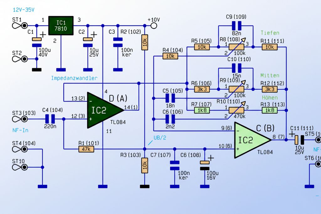
TL084 Hi-Fi stereo three-band tone control circuit schematic
The circuit is an active tone control stage designed to change the frequency character of the audio signal in three separate bands.
Being able to adjust bass, midrange, and treble separately provides more flexible use compared to classic two-pot bass-treble circuits.
It is especially useful in systems where the sound is heard as too muddy, thin, or dominant in the midrange due to the speaker, enclosure, and room acoustics.
Since the TL084 contains four opamps, a single IC is sufficient for stereo use. One channel is shown clearly in the schematic; the component numbers in parentheses indicate the corresponding components for the other stereo channel. This structure can be added as an input stage to tone-controlled stereo amplifier projects.
Power Supply Stage and Virtual Ground Point
A DC supply between 12V and 35V is applied to the circuit from the ST1 and ST2 terminals. The IC1 7810 regulator reduces this voltage to the +10V level.
C1 smooths the ripple at the input, C2 keeps the regulator output stable, and C3 transfers high-frequency noise to ground.
The TL084 is operated here with a single supply, not with a symmetrical supply. Therefore, a UB/2 reference at approximately 5V is created with R2 and R3 so that the opamp inputs and outputs can operate around the middle.
C7 and C8 fix this reference to ground in terms of AC. This point is not the real ground; it is used as an operating point inside the audio circuit.
Input Stage: Impedance Converter
The audio signal coming from the NF-In input is applied to the first opamp stage of IC2 through the C4 220nF capacitor.
C4 blocks the DC component at the input. The R1 47K resistor connects the opamp input to the UB/2 point, creating the correct operating point and largely determining the input impedance.
The first opamp stage operates as a voltage follower. The gain is approximately 1; the purpose is not to amplify the signal, but to drive the following active tone control network with a lower-impedance and stable source.
This approach reduces loading of the input source during potentiometer adjustments.
Active Three-Band Tone Control Stage
The second opamp stage operates in an inverting structure. Thanks to the resistor, capacitor, and potentiometer network placed in the feedback path, gain is increased or decreased in different frequency regions.
Therefore, the circuit is different from a passive RC tone control; it does not only attenuate the signal, but can also actively boost certain bands.
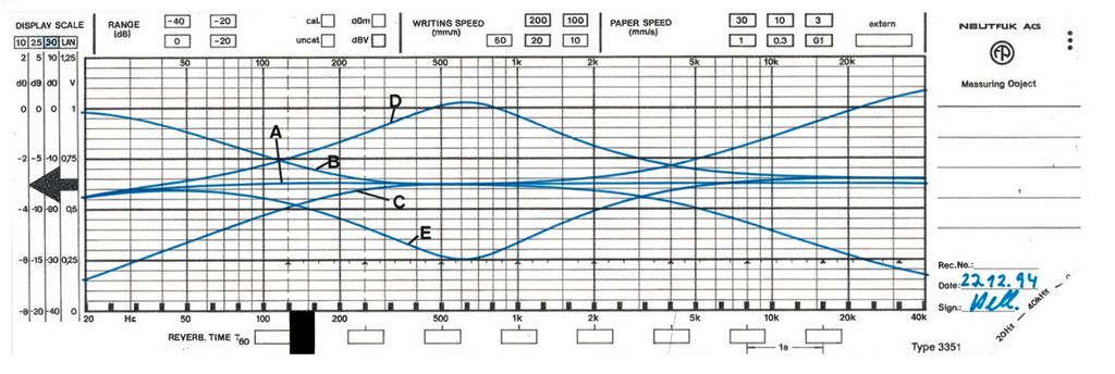
Frequency response curves of the tone control module at different potentiometer settings
Bass Adjustment
The bass section is formed around R4, R5, R8, R11, and C9. The R8 100K potentiometer is the bass control.
The C9 82nF capacitor allows the adjustment to mainly affect low frequencies by bridging the potentiometer differently at mid and high frequencies.
When the bass pot is in the middle position, the frequency response of the circuit remains largely flat.
When the potentiometer is turned in one direction, the feedback ratio of the low frequencies changes and the bass increases; in the other direction, the low frequencies are attenuated.
If the speaker enclosure is small or the bass region remains weak, this control can be used practically.
Midrange Adjustment
The midrange adjustment is made with R6, R9, R12, C5, and C10. The R9 100K potentiometer is the midrange frequency control.
While C10 15nF behaves differently against high frequencies, C5 18nF helps low frequencies be affected less by this adjustment.
The midrange adjustment is especially noticeable on vocals, guitar, speech intelligibility, and room resonances.
In circuits with only bass and treble control, it is difficult to correct the midrange separately; this three-band structure is therefore more useful.
Treble Adjustment
The treble control section is formed with R7, R10, R13, and C6. The R10 470K potentiometer is the treble adjustment.
The C6 2,2nF capacitor allows the adjustment to be effective in the high-frequency region.
If the treble adjustment is opened too much, recording noise, sibilance, and amplifier noise may become more noticeable.
If it is reduced too much, the sound becomes closed and dull. The most correct adjustment is made with small changes from the middle position according to the speaker and listening environment.
Output Stage and Coupling Capacitor
The signal coming from the tone control stage is transferred to the NF-Out output through the C11 10uF/25V capacitor.
Since the opamp output has a DC offset at the UB/2 level, a coupling capacitor is required at the output.
The polarity of C11 is important during assembly; its positive terminal should face the DC offset side at the opamp output.
The output signal can be applied to the input of a power amplifier, active speaker input, or preamplifier stage.
In more advanced audio systems, a similar active filter logic is also used in phase-corrected active crossover circuits, but here the purpose is not to separate frequency bands, but to change the tonal balance of the same audio signal.
Functions of Important Components
| Component | Value / Model | Function |
|---|---|---|
| IC1 | 7810 | Reduces the 12V-35V input supply to a +10V regulated supply. |
| IC2 | TL084 | Contains buffer and active tone control opamp stages for two stereo channels. |
| R1 / R101 | 47K | Determines the input impedance and the DC operating point of the first opamp stage. |
| R2 / R3 | 10K / 10K | Creates the UB/2 virtual reference point in single-supply operation. |
| C4 / C104 | 220nF | Passes the input signal as AC and blocks the DC component. |
| R8 / R108 | 100K pot | Allows bass frequencies to be increased or decreased. |
| R9 / R109 | 100K pot | Controls the midrange frequency region. |
| R10 / R110 | 470K pot | Adjusts the treble frequency. |
| C9 / C109 | 82nF | Determines the frequency character of the bass control network. |
| C10 / C110 | 15nF | Shapes the effective range of the midrange frequency control. |
| C6 / C106 | 2,2nF | Allows the treble control to be effective at high frequencies. |
| C11 / C111 | 10uF/25V | Blocks the DC offset at the output and transfers the audio signal to the external circuit. |
Technical Specifications
| Feature | Value |
|---|---|
| Circuit type | Active stereo three-band tone control |
| Opamp | TL084 quad-opamp IC with JFET input |
| Regulator | 7810 |
| Input supply | 12V – 35V DC |
| Opamp operating supply | +10V single supply |
| Current consumption | Approximately 15mA |
| Bass adjustment range | Approximately ±15dB |
| Midrange adjustment range | Approximately ±15dB |
| Treble adjustment range | Approximately ±15dB |
| Channel crosstalk | Above 80dB with suitable PCB layout |
| Total harmonic distortion | Below the 0,02% level |
Component List
| Group | Components |
|---|---|
| Resistors | 1,8K: R7, R13, R107, R113; 3,3K: R6, R12, R106, R112; 10K: R2, R3, R4, R5, R11, R102, R103, R104, R105, R111; 47K: R1, R101 |
| Potentiometers | 100K: R8/R108 and R9/R109; 470K: R10/R110 |
| Capacitors | 2,2nF: C6, C106; 15nF: C10, C110; 18nF: C5, C105; 82nF: C9, C109; 100nF ceramic: C3, C7, C107; 220nF: C4, C104; 10uF/25V: C2, C11, C111; 100uF/16V: C8, C108; 100uF/40V: C1 |
| Semiconductors | IC1: 7810 regulator, IC2: TL084 opamp |
| Connection parts | Solder pin, potentiometer connections, input-output and supply terminals |
Points to Consider During Assembly
- TL084 pin connections should be checked according to the manufacturer datasheet; if the IC is inserted backwards, it may be damaged when power is applied.
- The input and output capacitors of the 7810 regulator should be placed close to the IC.
- The UB/2 line is the reference point of the audio circuit; this point should be kept away from noisy supply paths.
- Using shielded cable for input and output cables reduces the risk of hum and noise.
- If chassis connections are arranged close to a star point, the possibility of hum is reduced.
- Power should not be applied before checking the polarity of the electrolytic capacitors.
How Is the Circuit Connected to an Amplifier?
The NF-In input is connected to the signal source, and the NF-Out output is connected to the input of the power amplifier. The circuit is not designed to drive a speaker directly; it only processes the low-level audio signal. A phone, Bluetooth module, DAC, preamp output, or similar line-level source can be connected to the input.
If the tone control circuit will be placed very close to the amplifier input, the cable length can be kept short.
If it will be used with potentiometers on the front panel, it is more correct to carry the input-output lines with shielded cable.
For simpler passive options, simple tone control circuit examples can be examined; however, this TL084-based structure offers a wider adjustment range.
First Startup and Test
- Before applying power, measure that there is no short circuit between the +10V line and ground.
- Apply a DC voltage between 12V-35V to the ST1-ST2 input and check that there is approximately 10V at the 7810 output.
- Approximately 5V should be measured at the midpoint of R2-R3.
- Apply a low-level audio signal to the NF-In input.
- When the potentiometers are in the middle position, a signal close to the input level and without noticeable distortion should be obtained at the output.
- The effect of each band should be checked by turning the bass, midrange, and treble potentiometers one by one.
- If DC voltage is seen at the output, the polarity and connection of C11 should be checked again.
Common Mistakes
| Mistake | Possible Result |
|---|---|
| Thinking of the UB/2 point as ground | The opamp operating point is disturbed, and clipping or silence occurs at the output. |
| Connecting electrolytic capacitors in reverse | Noise, signal loss, or capacitor failure may occur. |
| Using a long unshielded input cable | Mains hum and environmental noise increase. |
| Dropping the regulator input below 12V | The 7810 drops out of regulation, and the opamp operating point shifts. |
| Applying a high-level signal directly to the input | Clipping and sound distortion may occur at the TL084 output. |
Application Notes
This circuit is used most efficiently before the power amplifier. The order of source selector, volume potentiometer, and tone control may vary according to the design; in practice, the order of input selector, volume level, tone control, and power amplifier works without problems in most systems.
Since the TL084 is a low-noise opamp with high input impedance, it can be used in audio applications.
Nevertheless, if the PCB layout is weak, hum or channel crosstalk may occur regardless of the IC quality.
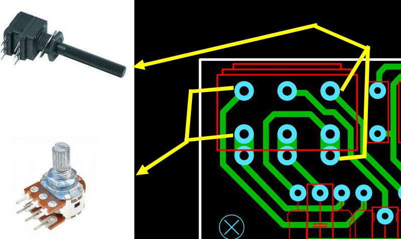
Keeping the potentiometer bodies close to the chassis, placing the supply bypass capacitors with short connections, and separating the input-output lines directly affect sound quality.
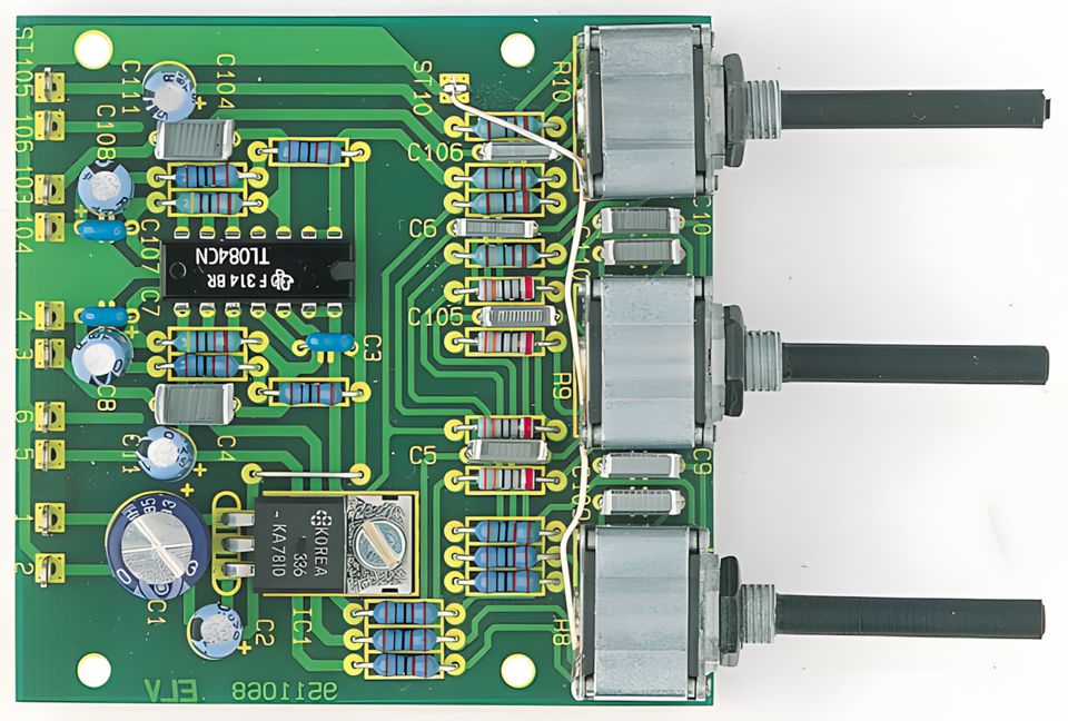
Note: The PCB drawing was made with the Sprint layout 6 program by copying it from the image in the PDF file. In addition, small changes were made in the PCB drawing to use classic narrow stereo potentiometers.
Source: de.elv.com/p/hifi-stereo-klangeinstellbaustein-P202596/


