This application step (step) motor control, input and output ports through 8051 will examine the circuit by providing lift.
We use our stepper motor circuit. As we know, certain steps of the stepper motor, moving the appropriate signals are sent to the windings of a motor coach that is brought to the desired position. About this circuit about 3 ° ~ 15.3 ° with a step angle of a stepper motor is used. And our program assigns the value 10 to the tour and variable speed of about 315 ° rotation of the engine have achieved.
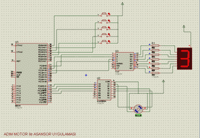
Stepper motors are available in the market as we know it ended the 4.5.6. We are in our circuit, we used 6-pin stepper motor. Therefore, we gave two ends to +12 volt supply. Our circuit is typically used to drive the stepper motor circuit, we used all the ULN2003. Thus, when applied to input logical “1”, all the circuits from the output of “0” is received and the motor is driven.

About half are 5 buttons. These buttons can be pressed in case our engine for each floor, how many times would return is known, because the last printed value, then the printed value of the difference between the taking, engine of our transfer we calculate and in this way our engine to the desired point income. The most recent published value compared to the value at that moment pressed, our engine up or down (left or right) will be decided to return.
8051 Elevator schematic

8051 Elevator Project Stepper Motor Control keil source code proteus isis simulation file: author: Zekeriya PEHLİVAN


8051 Robot ARM Stepper Motor Control
In this 8051 Robot ARM application I use for robot arm 3 stepper motor design, study and is to be informed about the expulsion. Stepping motors to provide work, applied to the ends of the half step mode and winding {1, 3, 2, 6, 4, 12, 8, 9} code sequence used. The last of the stepper motor has been used integrated ULN2003A. To determine the direction of movement of the Robot arm buttons are used. On the next page I wrote program robot arm step motors (joints) continues its move at the same time.
8051 Robot ARM schematic