
The design of a light source with a DMX interface, consisting of RGB LEDs panel, and thus able to illuminate objects with light of almost any color. Over 60 super-bright LEDs with up to 100,000 mcd luminosity were used in its construction. The device fits the KM-95 enclosure, which has a handle for mounting it to a wall or ceiling. Thanks to the modular construction (the device consists of a driver board and a board with LEDs), the controller can be powered by other LEDs, e.g. by supplying RGB strips and obtaining a different lighting arrangement. Recommendations: the lamp will be useful for people arranging the stage.
The DMX RGB lamp circuits are powered from the U1 pwm stabilizer built using the popular MC34063ACD integrated circuit. Thanks to this, the supply voltage of the system, and thus – LEDs, can reach 40 V, and the stabilizer will not heat up excessively, which would be the case when using a linear stabilizer. The U2 ICL7660 system generates negative supply voltages for the needs of operational amplifiers.
DMX control data is received using U6 (physical layer interface – MAX485), and then decoded using an Atmel ATmega88PA microcontroller. It generates PWM signals controlling current sources. Built using operational amplifiers and MOS transistors. Thanks to this, resistors with low resistance can be used, which means that energy losses are not high.
Due to the low channel resistance in the conduction state of the MOS transistors used, they also do not suffer large losses, which makes the heat sink unnecessary. The source current depends on the voltage at the non-inverting input of the operational amplifier and the value of resistance connected in series with the source of the transistor. For example, for the “green” channel (PwmG)
Schematic diagram of the RGB lamp with the DMX interface
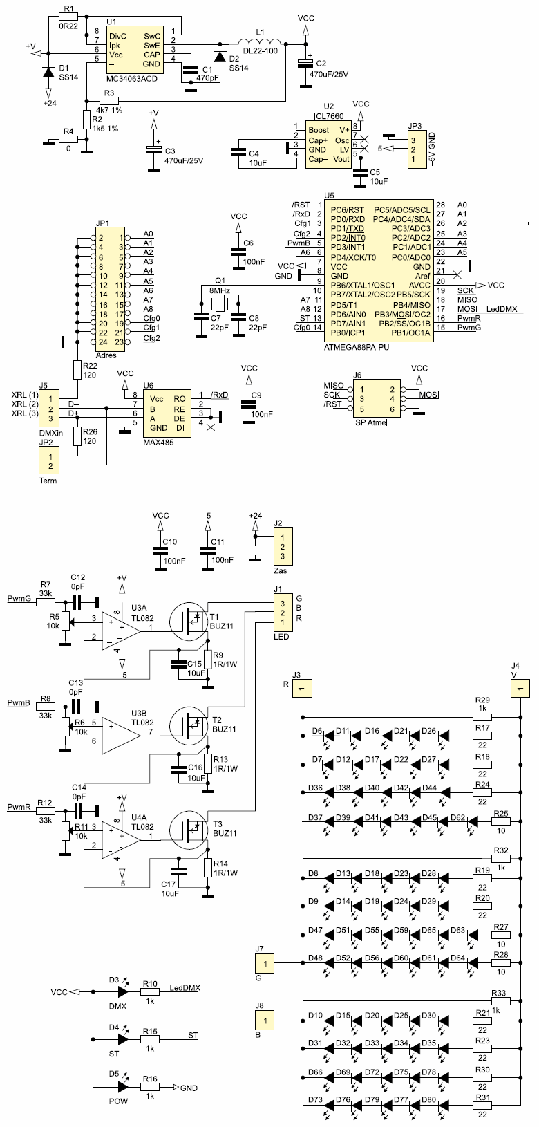
Orange is not recommended due to high power losses and/or the need to thicken the tracks. Parameters from the yellow fields can be obtained after changing the resistance R7, R8 and R12. For 2 V voltage at the non-inverting input of the amplifier, use 15kΩ, for 3V – 6.8kΩ, 4V – 2.4kΩ, for 5V 0Ω. These resistors together with capacitors C12, C13 and C14 form an RC filter.
The design uses C12 … C14 capacitors to eliminate harmful oscillations, however, prototype testing has shown that they are not necessary and should not be assembled. Their use would reduce the PWM signal slopes or even (at a high time constant) the formation of a constant component.
Capacitors C15, C16, C17 can not be mounted, but thanks to them during measurements the image on the oscilloscope is clearer. It is not necessary to protect the transistor gates against exceeding the Vgs voltage (depending on the 12 … 20V transistor), because the transistor will be fully open at a gate voltage of about 6.2 V and the operational amplifier will not allow further voltage increase.
The LED board, in addition to the LEDs, contains equalizing resistors connected in series in each branch. In addition, 1 kΩ resistors were added in parallel in each LED branch. Without them, it would not be possible to completely turn off the LEDs, because even at 0V at the current source input a certain minimum current flows through them, which is enough for a slight light of the LEDs. The LEDs are arranged in a “mosaic” such as TVs and CRT monitors.

![]()
FILE DOWNLOAD LINK LIST (in TXT format): LINKS-26359.zip


Lampe RGB ATmega88 avec interface DMX
La conception d’une source lumineuse avec une interface DMX, composée d’un panneau LED RGB, et donc capable d’éclairer des objets avec une lumière de presque toutes les couleurs. Plus de 60 LED super lumineuses avec une luminosité allant jusqu’à 100 000 mcd ont été utilisées dans sa construction. L’appareil s’adapte au boîtier KM-95, qui a une poignée pour le monter sur un mur ou un plafond. Grâce à la construction modulaire (l’appareil se compose d’une carte de pilote et d’une carte avec LED), le contrôleur peut être alimenté par d’autres LED, par ex. en fournissant des bandes RVB et en obtenant un arrangement d’éclairage différent. Recommandations: la lampe sera utile pour les personnes organisant la scène.
Les circuits des lampes DMX RGB sont alimentés par le stabilisateur pwm U1 construit en utilisant le circuit intégré MC34063ACD populaire. Grâce à cela, la tension d’alimentation du système, et donc des LED, peut atteindre 40 V, et le stabilisateur ne chauffera pas excessivement, ce qui serait le cas lors de l’utilisation d’un stabilisateur linéaire. Le système U2 ICL7660 génère des tensions d’alimentation négatives pour les besoins des amplificateurs opérationnels.
Les données de contrôle DMX sont reçues en utilisant U6 (interface de couche physique – MAX485), puis décodées en utilisant un microcontrôleur Atmel ATmega88PA. Il génère des signaux PWM contrôlant les sources de courant. Construit à l’aide d’amplificateurs opérationnels et de transistors MOS. Grâce à cela, des résistances à faible résistance peuvent être utilisées, ce qui signifie que les pertes d’énergie ne sont pas élevées.