
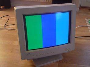
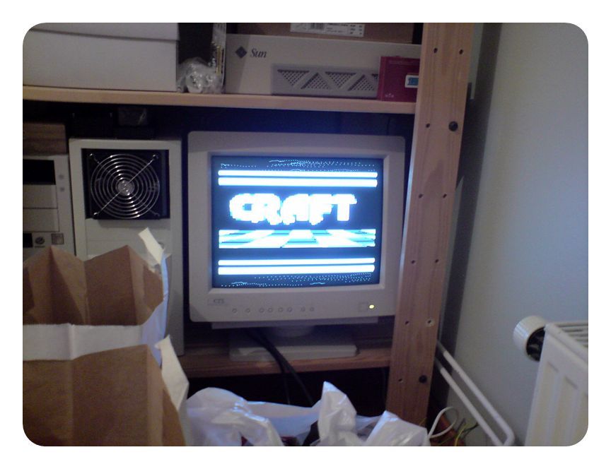
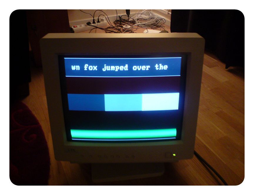
Classic monitor test circuits have a colorful image. In addition to this, there is a sound output from the music of old ateri games. It can be useful for amp tests 🙂 You will see when you watch the sample video
Sound signal generation : Sound is produced during horizontal dimming periods. This gives a sample rate of 31,496 kHz. Of course, only the really timing critical part (waveform generation) is performed during horizontal spacing. Melody, rhythm, amplitude envelopes, arpeggios etc. Vertical spacing is handled by a playback routine that is called once for each video frame.
There are a total of four audio channels, each with its own fixed waveform. Waveforms are 4-bit triangle, 50% pulse, 75% pulse and white noise. Noise is generated via a 15-bit shift register. The volume of each channel can be controlled individually, except for the triangular channel, which always plays at full volume.
Video signal generation: The VGA signal contains three analog voltage lines – red, green and blue – that vary from 0.7 V during the visible portions of the video frame. As you can see in the diagram below, I’m performing a two-bit digital-to-analog conversion using the R-2R resistor ladders for each of these signals. In this way, you can change the current color in a single clock cycle using the software out PORTC, register instruction.
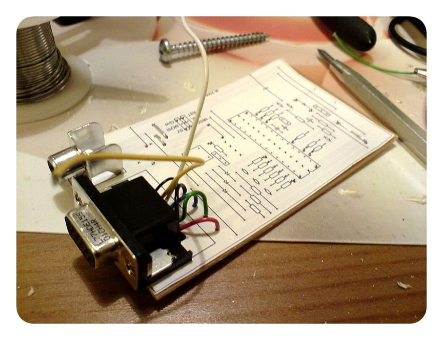
Monitor Test Circuit Diagram
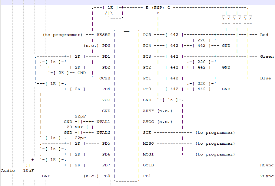
In addition, when the OC2B pin is high and the MOSI pin is low, the tri-color signal will be pulled to a high voltage. The MOSI pin is internally connected to a shift register (usually used for serial data transmission) in the AVR, and this shift register can be programmed to broadcast an 8-bit sequence with a string. Then smooth scrolling is implemented by adding variable delays before and after each screen line, but this alone is not enough because characters will suddenly appear and disappear at the edges of the screen. In addition, the output comparator connected to the ATmega88 timer 2 is set to generate a visibility window using the OC2B pin.
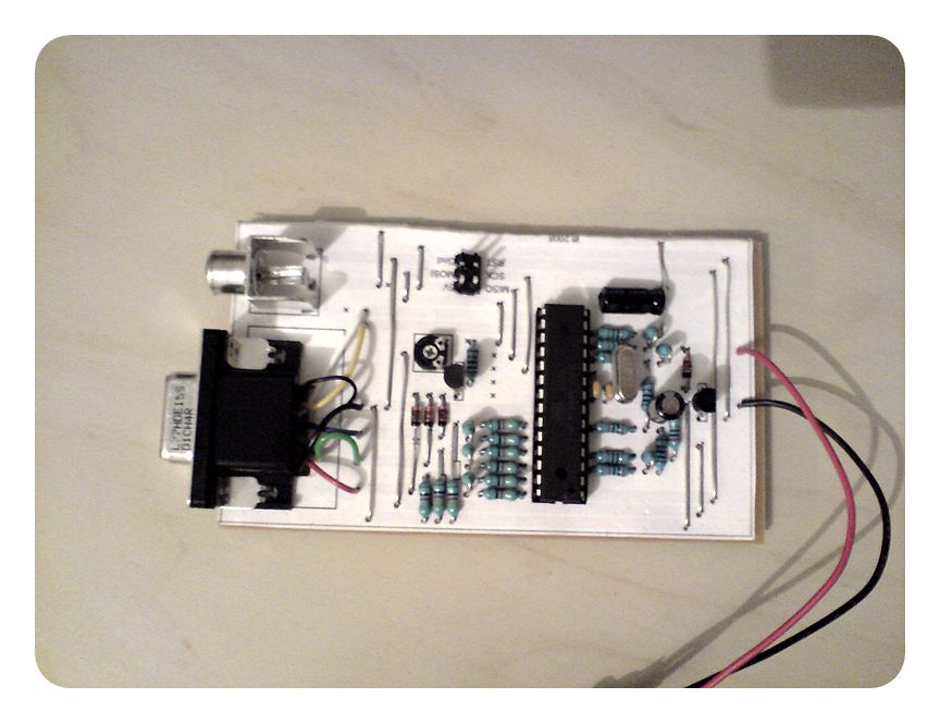
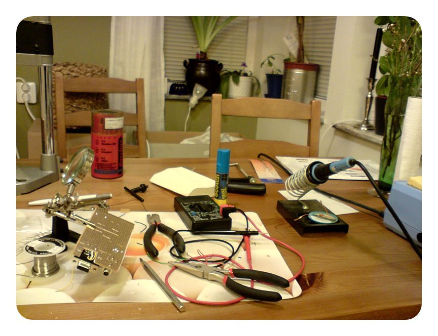
Monitor Test Circuit Work


Source: linusakesson.net Monitor Test Circuit with atmega88 alternative link:


0-2A 0-30V Regulated Power Supply Circuit
0-30 volt regulated power supply main parts of the TL081 opamp and transistors (BD243, BD139, BC548) In addition to the display indicator volt meter circuit ICL7107 made with voltmeter power solid apart from the used power supply and voltmeter circuits Eagle prepared with PCBs schema files there. Laboratory-type power supply will do the trick in many projects.