A very interesting project, digital solid At-mega8515 at-tiny12 has source software files and schematics, pcb drawings. It can give different ideas for people working with Atmel series microcontrollers, analog solid can be useful in different projects
Signal generation method
The ATmega 8515 microcontroller is used as the basis of the device. The microcontroller program can be divided into two parts. The first is the main loop, which processes incoming characters and stores their formats in external memory, and the second part is the interrupt handler, which generates the video signal.
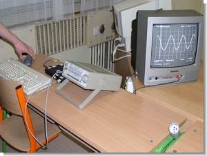
TV Oscilloscope Project

There must be an interruption exactly every 64 ms (the duration of a line) so that the image does not tear. Initially, a line sync pulse is always generated (if there is no line with a frame sync pulse). Wait about 8 ms (dimming pulse) and start transmitting data. After the data is transmitted, the interrupt is terminated.
The problem arose with the different timing of the instructions in the main program. Instructions can take 1 to 4 instruction cycles2. The interrupt occurs only after the end of the given instruction, and therefore the onset of the interrupt can differ by up to 333 ns, which is already visible when using a 12 MHz crystal in the processor.
Therefore, the program uses two interrupts. The first interrupt comes every 64ms (duration of a line). This “prep” interrupt has quick instructions that take 1 to 2 cycles to line up the received characters.
During this interrupt comes a “main” interrupt that sends data and sync pulses. The screen resolution is 256 x 256 pixels. The device allows you to display data on the screen in four colors. Therefore, each pixel on the screen is represented by two bits in memory. Thus, a Byte displayed on the screen consists of two Bytes selected from memory.
A line on the screen is represented by 32 Bytes with 64 Bytes in memory. The data then occupies 16,384 Bytes to render the entire screen. Such amount of data will not fit in the Atmega 8515 microcontroller, so an external memory is connected to it, which is used to store the displayed data.
32 KB memory was chosen for economic reasons. This memory needs 15 pins to address memory space and another 8 pins for data transfer. Such a solution will disproportionately occupy many pins of the microcontroller, so a D-type capture memory register is used that allows the lower 8 bits of the address. . This is stored in the register and later these pins can be used by the microcontroller to work with the data.
The lower part of the address appears first on the PA port. This is followed by an ALE pulse that writes the lower bits of the address to the D register (IO 74HC573). The upper part of the address is set in the PC port. Data can now be set to write and write with a WD pulse or read with an RD pulse. The given link is taken from [4.].
256 pixels are displayed in one line in 44 ms. This means that every 170 ns another pixel must be sent. This corresponds roughly to two instruction cycles. The microcontroller cannot send data that fast, so data is sent through two 74HC166 shift registers.
To save pins and time, these registers are connected to the same bus as external memory. The advantage is that the microcontroller itself generates an impulse to write to the shift registers with the WD signal. During data storage, when not displayed, the records are permanently reset and do not send any data to the screen.
The signal for the shift register clock input is generated directly in the microcontroller. This is a T0 timer set to produce a 6MHz square wave on pin PB.0.
The resulting video signal should consist of sync pulses and data so that the output voltage is 0 V during sync pulses, 0.33 V when creating a black point, and 1 V when drawing a white point. The resulting signal is created using resistors and diodes.

source: radim.xf.cz TV Oscilloscope Circuit with ATmega8515 ATtiny12 schematic code files alternative link:


LM3886 TDA7294 Bridge PCB
Previously normal for LM3886 and TDA7294, for bridge connections but this feature of the project was shared circuits designed to bridge the connection of PCB layout drawings and small size of the smooth double-sided construction drawings to be as bad a little difficult
My first attempt at a double-sided PCBs had a bit lot of tiring effort separate upper and lower sections for easy connection element section çıkatıp to pierce plaque plaques pasted in certain areas
PCB used photoshop to make it suitable for printing Drawing
LM3886 TDA7294 Bridge