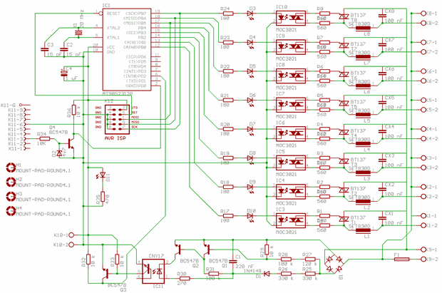
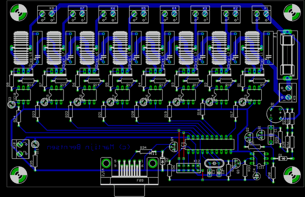
AT90S2313P 200 watt Dimmer Circuit is controlled from RS232 Port MOC3021 Opto Triac driver isolated control program works on xp. It’s very simple. Hex asm codes for AT90S2313P are pcb schematics, there are also source code files of the pc program. rs232dimmer.asm, rs232dimmer.hex, dimmer.vbp, dimmer.vbw, dimmer.frx
Warning: This circuit is connected to the mains voltage: This voltage is life-threatening if touched. so only practice if you know how to handle it safely.
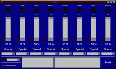
With this circuit, you can change 8 lamps on your computer. Each channel is maximum 200 watts. The circuit is connected with the computer via the com port. The AVR controls the moment the triac starts transmitting. To do this, it must know when each half of the sinus begins. The circuit used for this is called a zero crossing detector. This circuit outputs a pulse every time there is a zero crossing. average Because this circuit also depends on the mains voltage. It has an optocoupler inside to optically separate it from the rest.
PC Controlled Dimmer Circuit
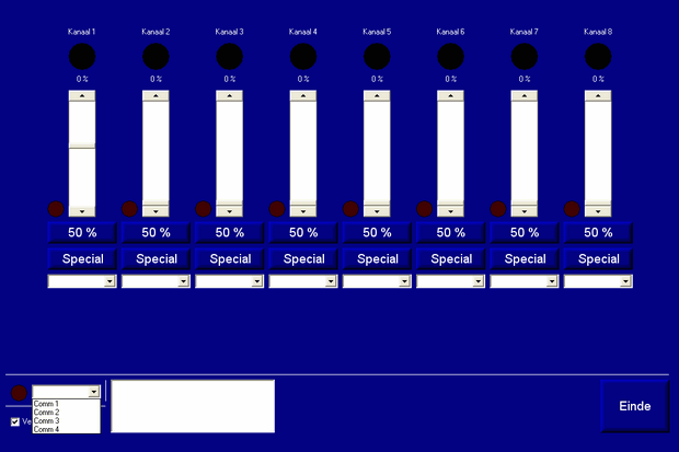
8 channel mains dimmer
The heart of the dimmer is a ATTiny2313. the AVR performs three tasks: – It receives new data via the com port, – He receives pulses and the power of positive to negative goes and vice versa, this is called the zero crossing. – He makes 8 pulse-width modulated signal (PWM) with a frequency of 100 Hz. these signals are equal to the zero crossings from the mains.
The PWM signals control 8 optotriacs. These are optocouplers but with a built-in low power triac which can switch. In this project be MOC3021 optocoupler used. You can also add other optotriacs use as long as they have no zero-crossing detection, because working not if you want dim.
source http://www.aavrs.nl/projects.php?p=1 Computer Controlled 8-Channel Dimmer Circuit pcb schematic avr source code pc program alternative link:


Cabin Control with PIC18F2550 PIC18F2520 CCS C
Two interesting projects Inverer the-PIC and Terra PIC terra abviously with pets or aquarium cabinet temperature of the light feeding control enables Inveria the air control may be associated with exactly can not bring my project to publish reasons CCS prepared with source code and Orcad files that I did not understand my PIC Programming could be useful for dealing with our friends. Isis also came prepared with layers of simulation files in the library’s code a project that will benefit in every way