Amplifier for RGB strips The dynamically developing field of LED lighting means that a whole range of devices related to such applications is needed. One of them is the amplifier described here, which allows you to increase the current efficiency of the controller.
Scheme of the RGB LED strips amplifier is shown in Figure 1. The device has the following parameters:
Tape control with a common anode.
+12 VDC power supply.
Three independent channels.
No logic level inversion between input and output.
Regeneration of the control signal edges.
Small dimensions, allowing closure in a heat shrink tube.
The amplifier is composed of three identical functional blocks, each of which contains: MCP1401 integrated circuit, 1mF ceramic capacitor, MOSFET-N transistor, IRF7201 type.
Schematic diagram of the amplifier for RGB strips
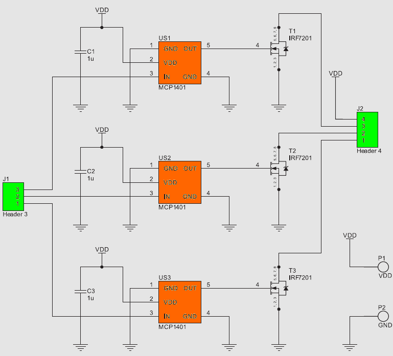
An integrated driver was used to control the power transistor’s gate, because the circuit consisting of discrete components performing the same function would occupy much more space on the board.
The controller includes a Schmitt trigger that forms the slopes of the control signal, which limits power loss during switching. The input is the gate of the MOS transistor, therefore it is not a load on the control system. An additional feature is the signal inversion (MCP1402 is a non-inverting version), which, in combination with the fact that the final transistor is in a common source circuit, means that the whole circuit does not reverse the phase.
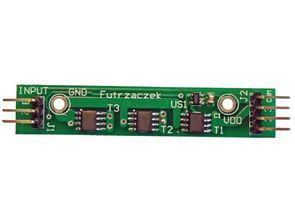
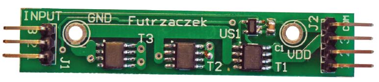
Figure 2. Assembly diagram of the amplifier for RGB strips
The ceramic capacitor was placed as close to the control system terminals as possible and is an element required by the manufacturer. It reduces supply voltage ripple when transistors’ CGS capacity is reloaded, i.e. during a slope.
The IRF7201 transistor is characterized by low RDSon open channel resistance (at 30mΩ) and a high continuous 5.8A drain current (at TC housing temperature = 70 °C). It is available in the SO-8 housing.
The system was assembled on a double-sided printed circuit board measuring 63×12 mm. The elements were placed on both sides of the board. In the prototype system, male pin connectors have been soldered as J1 and J2, which allow convenient soldering of wires or insertion of connectors.
Due to the width of the paths, the basic version can transfer currents up to approx. 3A per channel. To increase its capabilities, you must thicken the power and lead paths to J2. It is recommended that, if possible, the common cable of the tape supplied from the amplifier should not be connected to the J2 connector, but directly to the P1 pad.
The power lost in the system is small – with a current flow of 3A and a 12V supply, the voltage drop was only 120mV. In addition, the rate of rise of the edges of the input signal does not affect the operation of the system, because it is able to regenerate it.
where the blue waveform is the input voltage and the yellow waveform is the voltage on the drain of the output transistor. The measured rise time is 150 ns, and the fall time 9 ns – with an oscilloscope rise time 6ns.
![]()
FILE DOWNLOAD LINK LIST (in TXT format): LINKS-26344.zip


Amplificateur pour bandes LED RGB
Amplificateur pour bandes RVB Le domaine en développement dynamique de l’éclairage LED signifie que toute une gamme d’appareils liés à de telles applications est nécessaire. L’un d’eux est l’amplificateur décrit ici, qui vous permet d’augmenter l’efficacité actuelle du contrôleur.
Le schéma de l’amplificateur à bandes LED RVB est illustré à la figure 1. L’appareil a les paramètres suivants:
Contrôle de bande avec une anode commune.
Alimentation +12 VDC.
Trois canaux indépendants.
Pas d’inversion de niveau logique entre entrée et sortie.
Régénération des fronts du signal de commande.
Petites dimensions, permettant la fermeture dans un tube thermorétractable.
L’amplificateur est composé de trois blocs fonctionnels identiques, contenant chacun: circuit intégré MCP1401, condensateur céramique 1mF, transistor MOSFET-N, type IRF7201.
Schéma de principe de l’amplificateur pour bandes RGB
Hello,
will this work with Arduino? Arduino-> RGB amplifier-> RGB LED
Thank you
Hello,
yes it works.
also a different circuit;
https://320volt.com/rgb-serit-led-uzatma-devresi/