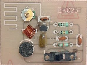
I’ve shared this with a simple fm transmitter circuit, this circuit has been pretty nice drawing layout of printed circuit boards used in antenna pcb antenna, or normal tape prepared by drawing on over 5.10 cm can be achieved better results by attaching the wire ring. L1 on a pencil on the winding circuit 6 laps a coil that is set between 2-22pf capacitors (trimer) you can set the frequency of the publication. The circuit works with 9 volts.


Source: electroschema.blogspot.com/2011/08/schema-micro-espion-fm-88-108-mhz.html


Microchip Development Test Board PIC18F452
Microchip microcontroller users is quite a useful experiment to work you need a Pic18f452 development Board this way, small-sized double-sided printed circuit board drawing a lot of property has been added … max232 rs232 connection, boot loader, 24c256 eeprom, LEDs, buttons, he16m, lcd, DS1307, etc. also boot loader program code (Pic Basic Pro included) have the schema files, pcb drawings.