you can see in the circuit diagram circuit, which runs between 5- 15V two 70 -watt lamp brightness increased or decreased . 1X1 and 1X2 circuit power supply input terminals of the ends and between 5- 15V input must be provided. 2X1 and 2X2 ends are the ends of the lamps to be connected .
C3 is kondansitör kondansistör supply . 555 timer circuit I01 is the main controller . This timer can operate with a maximum of 15V DC . So a higher voltage to be given to the timer circuit to malfunction may result . P1 , R1, R2, C1 and C2 supplies a timer to work properly, the indispensable materials.

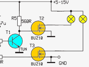
P1 potentiometer position is changed will change in frequency at the output of the timer lamp brightness to be changed . The circuit diagram of the timer output can by two bulbs with resistors R3 and R4 is bifurcated .
Here, R3, R5 and T1, T2 materials and attached to an end gate of MOSFET T1, T2, MOSFETs are used as the driver transistors . T3 R4 resistance of the MOSFET is driven. The drain of the MOSFET T2 and T3 ends lamps , source terminals are connected to the chassis . The purpose of using the MOSFET circuit is related to the current drawn .


H Bridge 12V 100W Motor Driver Circuit Project
You can see in the diagram 100w motor control circuit with DC +12 V circuit. HCF4098 is provided by the engine control circuit . Cd4098 inside the double precision has a monostable multivibrator . ( I02 and I02B ) Device for application of a voltage limitation that can be reset and re-triggered provides webpages . RX and CX external resistor , a capacitor can be adjusted with an external timing control is provided. RX and CX values Q and Q ‘ outputs and adjusts the pulse width are independent of each other . R5 is a resistor divider .